Doublelock Sensor
Sometimes you’re laying in bed and your are almost sure that the front and back door are on the doublelock, you ask your wife did you check the doors and she answers I thought you did that.
From that moment you can’t sleep because your not 100% sure you locked the doors properly with the doublelock. The only thing left is getting out of bed and go downstairs to check the locks, then they are always locked, but if you do not check if they are locked then the door is unlocked for the whole night.
A simple led in the Node-red dashboard on my phone or a physical led in the bedroom to check if the doors are locked and you can go sleep like a princess. Because the status of the doublelock is now known in Node-red you can do everything with it.
The mechanical part of those kind of projects is the biggest challenge. How can you measure reliable if the door is double locked. You can buy locks with a build in sensor, but then you have to adapt your door and/or door frame and bring a thick chequebook.
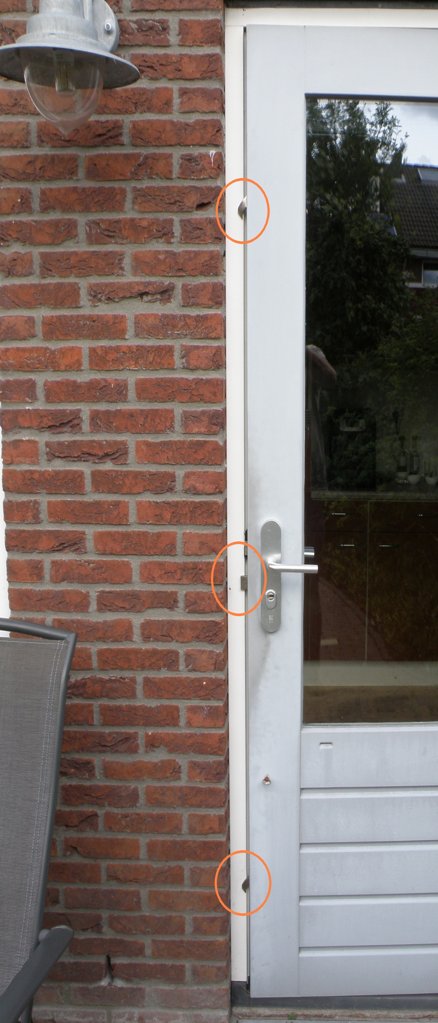
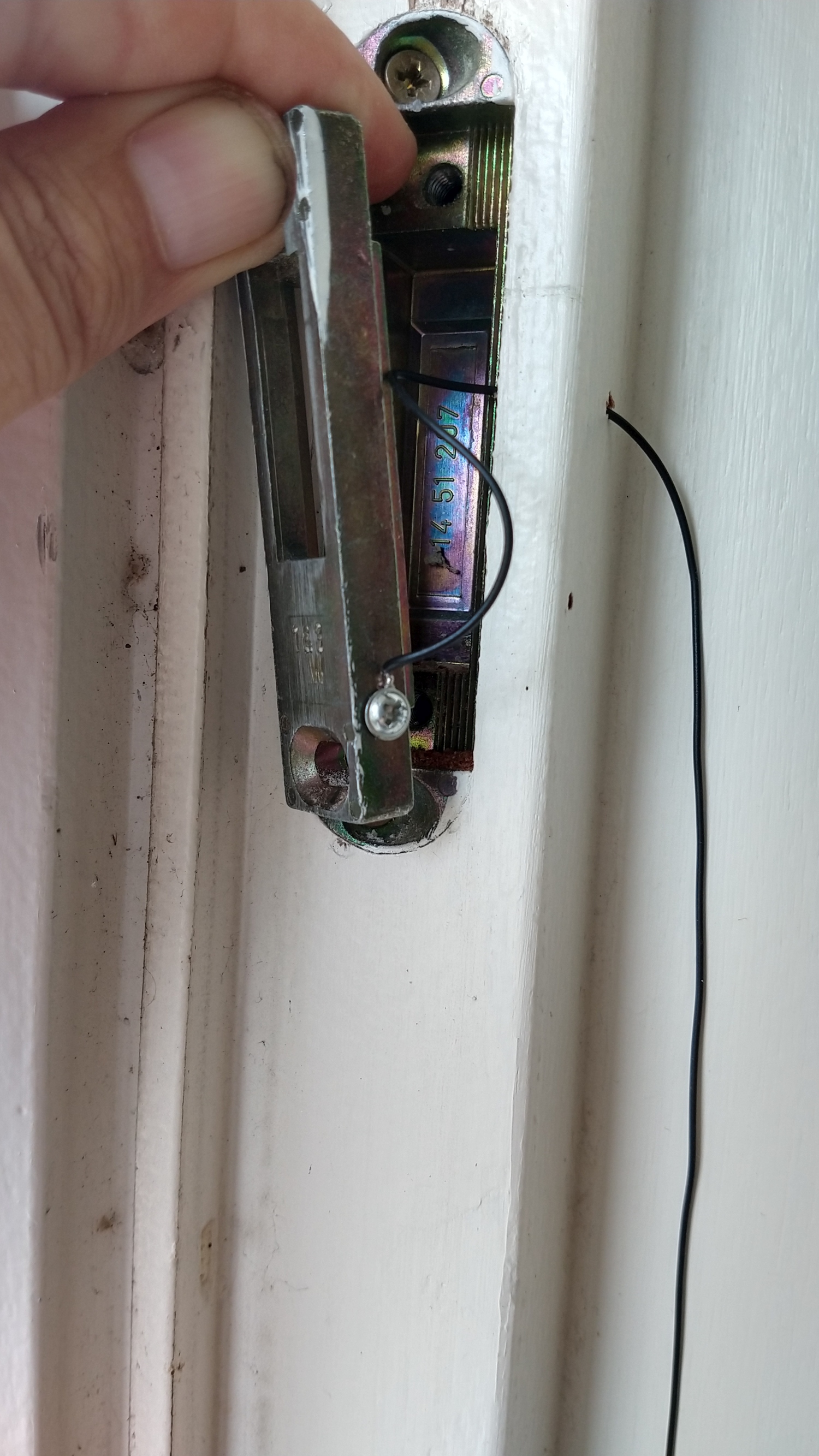
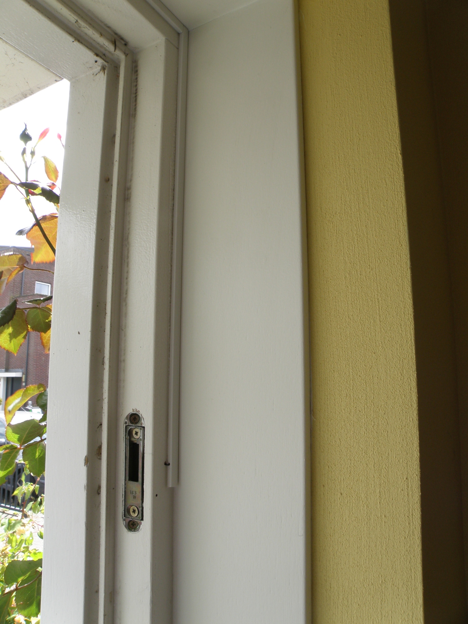
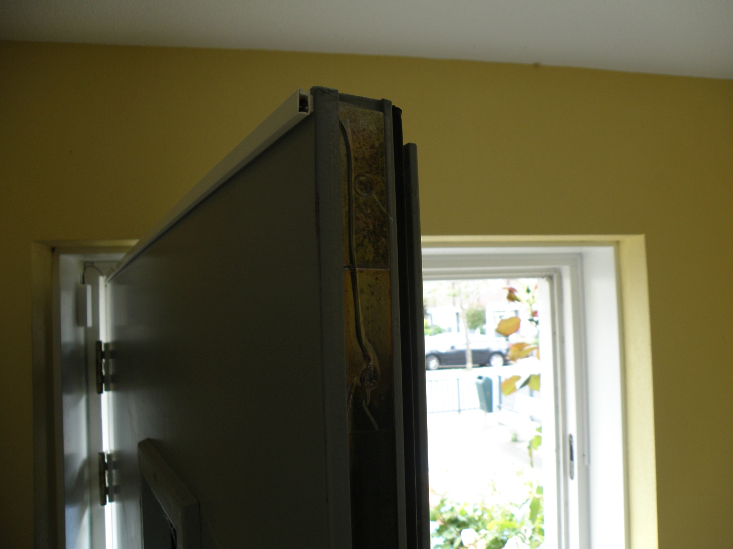
The lock I have is of the type (Dutch: 3 punts sluiting) 3 point closure lock, see picture. That means that the door is locked on 3 points for maximum security. The top and bottom lock hook is designed so they push the door towards the door frame for a tight closure. Those hooks will hook in a metal lock tray. When those hooks are out and making (electric) contact with the lock tray you are sure that the door is locked and on double lock.
So measuring if there’s an electrical connection between the hook and metal tray will be the best and easiest way to do this.
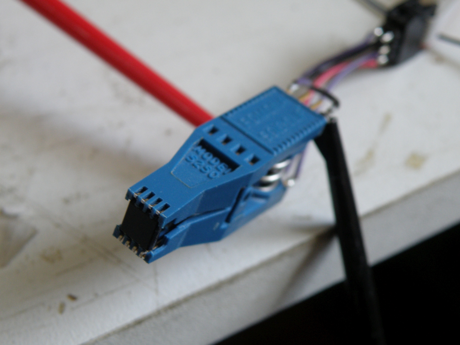
The idea was to use an of the shelf 433Mhz wireless door/window burglar alarm sensor and replace the reed switch with the “hook” and “tray” contact. Important was that this sensor can detect opening and closure, not all 433Mhz will send an unique code for both events. My choice was the GS-WDS07 sensor that you can find for example on Banggood. It runs on a single AAA battery, and this battery should last for at least 3 years, see below for my findings. The last digit of the code send by the GS-WDS07 will determine what the message is.
| 13F70A | Open |
| 13F70E | Closed |
| 13F707 | Tamper |
| 13F706 | Low battery |
As receiver for the 433Mhz signal I’m using a Sonoff RF-bridge with Tasmota software and Portischs firmware for the rf chip inside. With Tasmota it’s very easy to get all the data from the sensors in Mqqt and Node-red.
Installed the wiring and sensor, all works perfect. When the door is double locked the sensor led becomes green and if not locked the sensor becomes red.
However after using the sensors for 7 months, very rare the sensor stops working and you have to remove and reinsert the battery to get the sensor going again. This makes the sensor and the whole idea unreliable, you can’t trust the state of the indicator any more, bummer, still have to go downstairs to check the doors.
Because the sensor only sends data when the state changes, and that can be sometimes ones in 2 days, it’s hard to determine if the sensor is alive. I need something that will give “i’m still alive” message every x time. With this message you can make something simple in Node-red that will notify me when the sensor is off line.
After initial thought like making my own sensor with an ESP8266 or Avr with rf module, I came to the idea to use the unpopulated tamper switch of the GS-WDS07 sensor.
Activating the tamper switch every 15 minutes will send a code that we can use for this purpose.
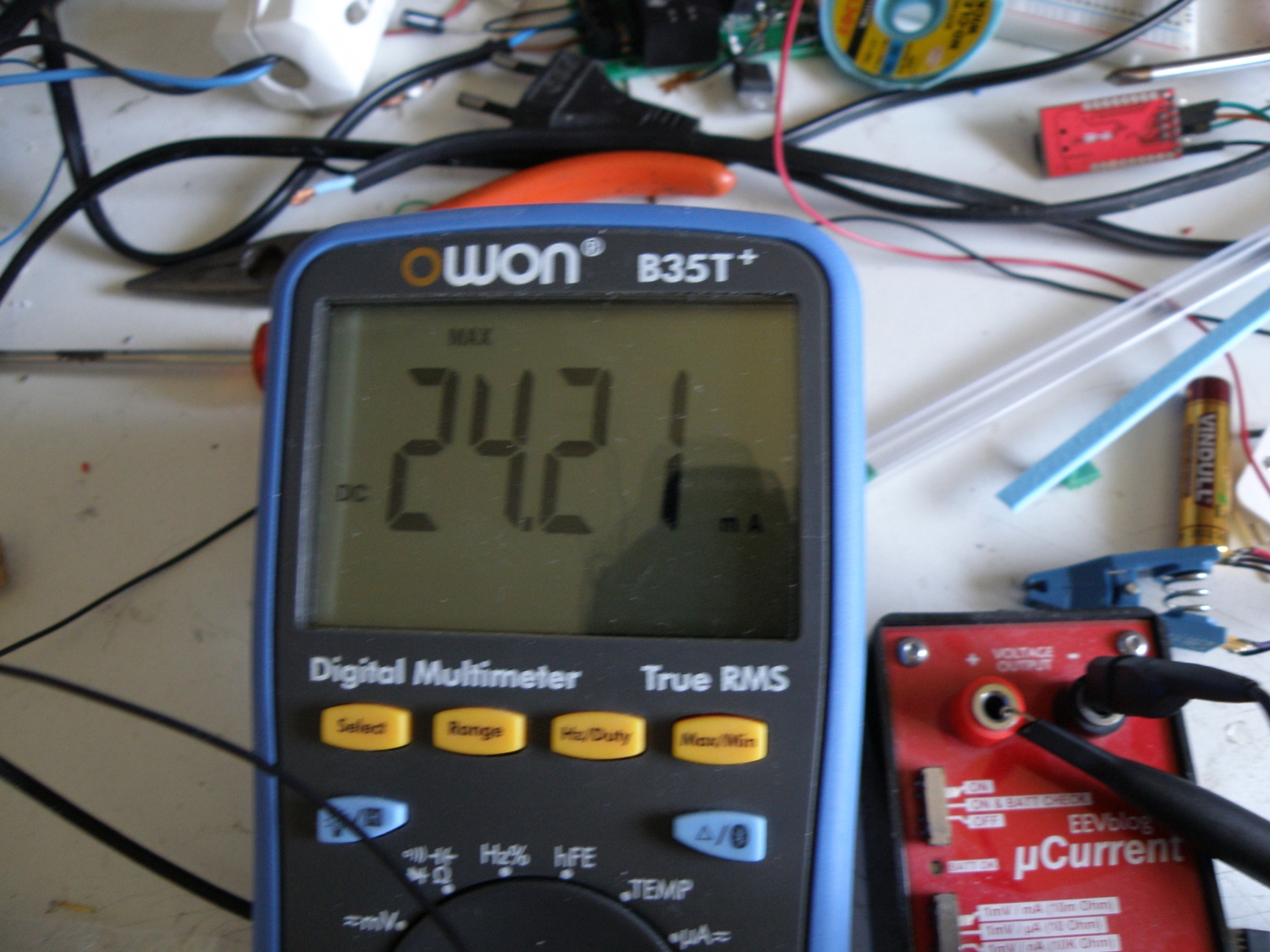
To get this job done a Tiny45 avr processor with some software was added to the sensor, to save energy the avr had to draw a low current as possible. The Tiny45 draws only 4µA when sleeping with the watchdog timer enabled, adding this to the 36.8µA that the sensor was using, isn’t a big issue.
Internally the sensor runs on 3.3V, so giving the attiny45 some power isn’t also a big problem.
The tamper switch signal pin was internally pull-up to vcc, to activate the tamper signal this has to be grounded. The Bascom code will wake up every 15 minutes and pull the tamper switch signal to ground for 50ms and goes back to sleep after setting the pin back as input to prevent energy use.
An AAA battery has a capacity around 1500mAH, the sensor can run 1736 days on this. However there will be now a “i’m alive” transmission every 15 minutes. This transmission takes 1.4Sec and consumes 24mA peak. This is around 40µAH, add this up to the 40µAH the sensor was consuming and you can still run 868 days on 1 AAA battery. That’s fine with me. I love doing low power projects with Avr.
Developed the code in Bascom Avr, on of my favourite compilers that I’m using now for more then 20 years.
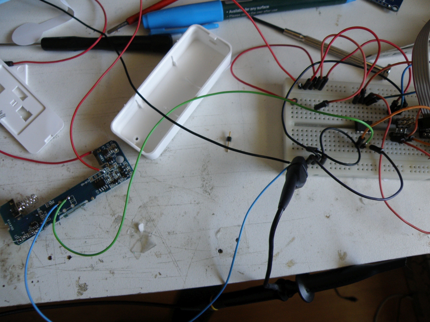
Made a little test setup with a dip version of the tiny45 on a breadboard, after writing and testing the code flashed it in a smd tiny45 and soldered that in sensor.
Job, done.


Used Bascom code.
'#####################################################
' Door sensor "is alive" hack
' EvertDekker.com 2020
' V1 20200531 Bascom 2082
' Thanks to EDC for the nice watchdog example
'#####################################################

$PROG &HFF,&H42,&HDF,&HFF' generated fuse bit settings.
$regfile = "attiny45.dat"
$crystal = 1000000
$hwstack = 64
$swstack = 16
$framesize = 64

Config Portb = Input                                       'to Reduce Power , Setup All Pins As Inputs With No Pullups

Adcsra.aden = 0                                             'Disable a/d convertor
Acsr.acd = 1                                                'Disabel analog comperator
Didr0 = &H3F                                                'Disable digital input buffers on all ADC0-ADC5 pins
Prr.pradc = 1                                               'Power adc disable
Prr.prtim0 = 1                                              'Power timer0 disable
Prr.prtim1 = 1                                              'Power timer1 disable

Const Minutsleep =(15*60)/8.192                            '15 minutes * 60 sec / 8.192

Dim Sleep_cnt As Byte

Config Watchdog = 8192                                      ' ~8s"
Start Watchdog
On Wdt Wdt_isr Nosave
Enable Interrupts


Do

   If Sleep_cnt = 0 Then
      Sleep_cnt = Minutsleep                                 'Set counter back to start value
      Config Portb.3 = Output                               'PortB.3 as output
      portb.3=0                                               'Pull it low to activate the tamper input
      waitms 50
      Config Portb.3 = input                                'PortB.3 back as input to prevent energy use
   Else
      Decr Sleep_cnt
   End If

   Enable Wdt
   Config Powermode = Powerdown                            'Will go to sleep here

  'here uC will start after wake up

Loop

Wdt_isr:
 'dont enable Wdt here
Return