How to replace Xbox360 Benq lens
Required tools: Philips screwdriver 00 & 0 ,flat 1 and soldering iron.
The Benq VAD6038 drive is used in some xbox360 units. The quality of this drive various very much due the lens unit. Some unit last forever, other break down within a month. If you have warranty bring it back to M$. Are there reasons that you can’t bring it back, we have here a Diy tutorial for you. New lens units are wide spread available on the net and will cost you between €20,- and €30,-.
The laser or also called lens is a very sensitive device for mechanical stress and static charge. Don’t use force and keep yourself discharged with a wristband. Don’t touch the optical lens with your fingers.
It’s not a difficult job, but if you don’t have experience in repairing fine mechanical component don’t do it and never blame me if you mess it up.
Opening the Xbox360 and removing the drive are not explained here, there are enough tutorials available on the net.
Lets get started
The tray must be open to get access to the lens, you can choose to open the tray by pushing the tray open button when your xbox is still in 1 piece or you can open later the tray by hand.
 |
 |
 |
| Step 1 | Step 2 | Step 3 |
First remove the 4 screws at the bottom (step 1) of the drive and cut the warranty seal . Now you can take the drive apart by removing the top and bottom metal case.
If you didn’t open the tray before then it’s time to do that now. On the front of the drive is just below the tray a small rubber wheel. It’s difficult to see on the picture (step 2) but you will see it. Turn the wheel gently to the right, the laser unit will be lowered and the tray will open slowly. If the tray is about 2cm open you can pull gently on the tray to fasten the opening process.
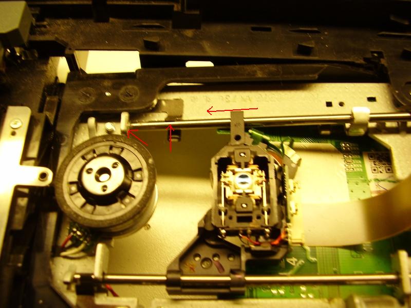
There it is, the lens that gives you all that problems(step 3).
To keep the rest of this tutorial clear put your drive just like I did, with the tray to the left.
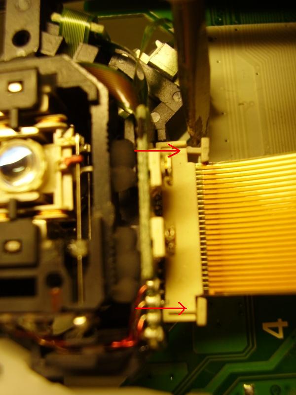
Remove now the 2 clamps as marked in step 3, one in the upper right corner and the other in the lower left corner.
 |
 |
 |
| Step 4 | Step 5 | Step 6 |
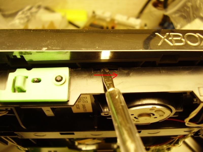
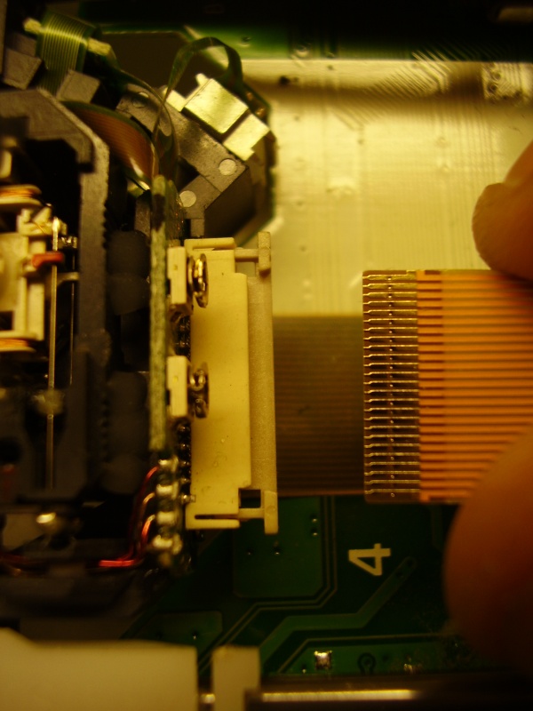
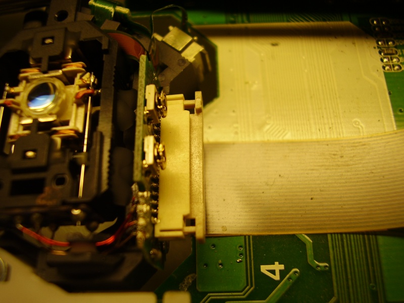
Disconnect now the flat cable from the lens unit (keep yourself discharged !) by gently push the lock (step 4) to the right with a small screwdriver. Repeat this for the other lock, the flat cable will now come very easy lose (step 5).
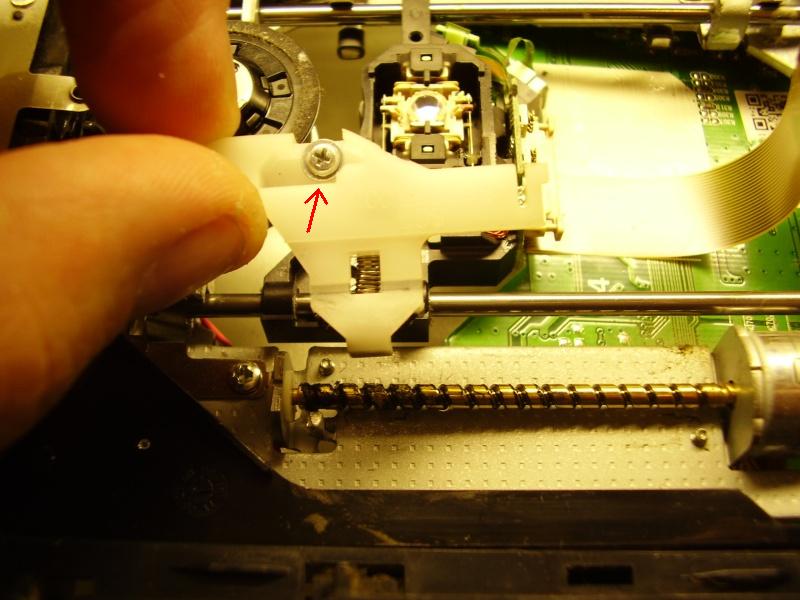
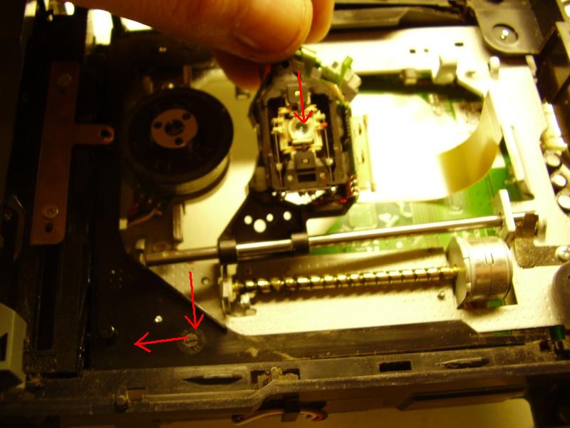
Let’s remove now the driving unit by losing the screw and lifting it(step 6). Watch out that the spring will not jump away.
 |
 |
 |
| Step 7 | Step 8 | Step 9 |
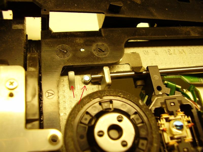
Now we can remove the slide axles and the lens unit. First we must remove the back axle by lifting it up at the right side and push it 5mm to the north and then slide out the axle to the east(step 7). The clamp is the upper left corner (step 8) is still pressing on the axle so you feel a little bit resistance.
The lens unit can now easy be removed by lifting it in a 45 deg angle. Lift now the front axle up on the left side and pull the axle with the lens unit out to the west.
Disassembling is now finished, let’s put it back together.
 |
 |
 |
| Step 10 | Step 11 | Step 12 |
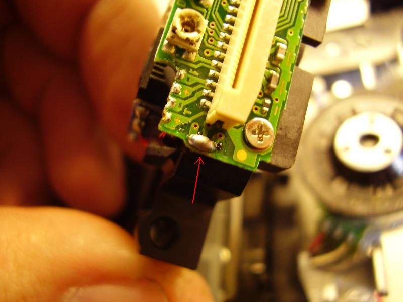
The lens is shipped with a short circuit to protect it against static electricity. Is the clump solder show on the picture(step 10), this must be removed otherwise the lens won’t work. It’s the best to remove the clump as finale step thus after connecting the flat cable.
Slide the lens unit on the axle and insert the axle angled under the clamp in the lower right corner to the east (step11). Hook the axle under the bracket at the left side and then place the clamp back in the lower left corner (step 12). The front axle is now finished.
 |
 |
 |
| Step 13 | Step 14 | Step 15 |
Let’s put back the back axle. This is the most difficult part to do, or maybe only to explain ?
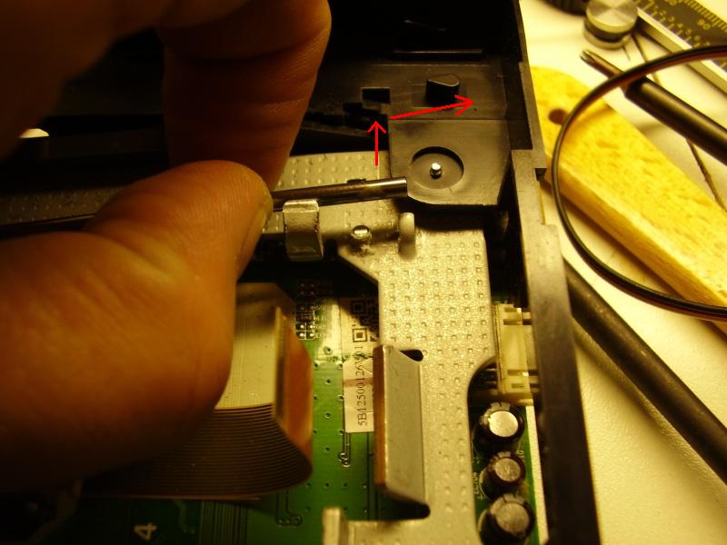
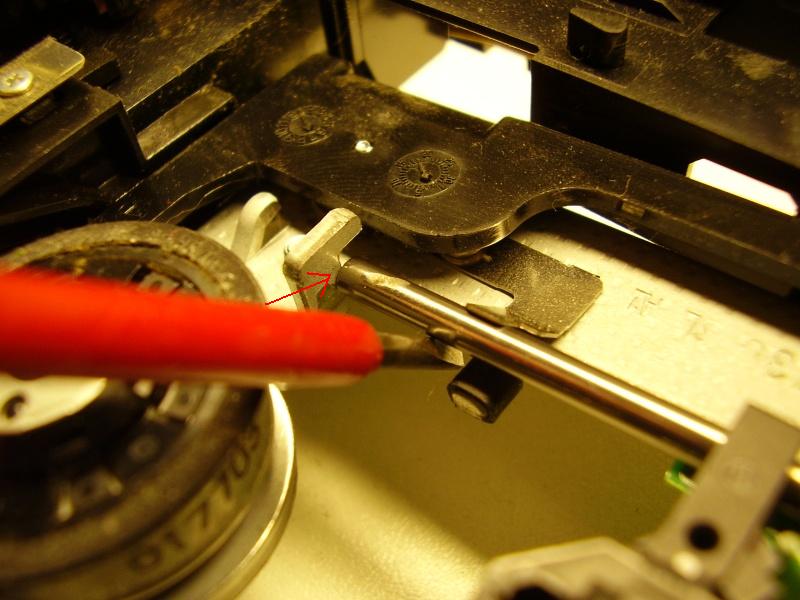
Slide the axle from the east to the west trough the lens unit, then under the clamp in the upper left corner (Step 13). The axle will now hit a metal bracket, lift it gentle up so it can pass it (step 14). Sliding the axle further to the west it will meet a screw, lift it gently up again (step 15) to get it over. Almost finished.
 |
 |
| Step 16 | Step 17 |
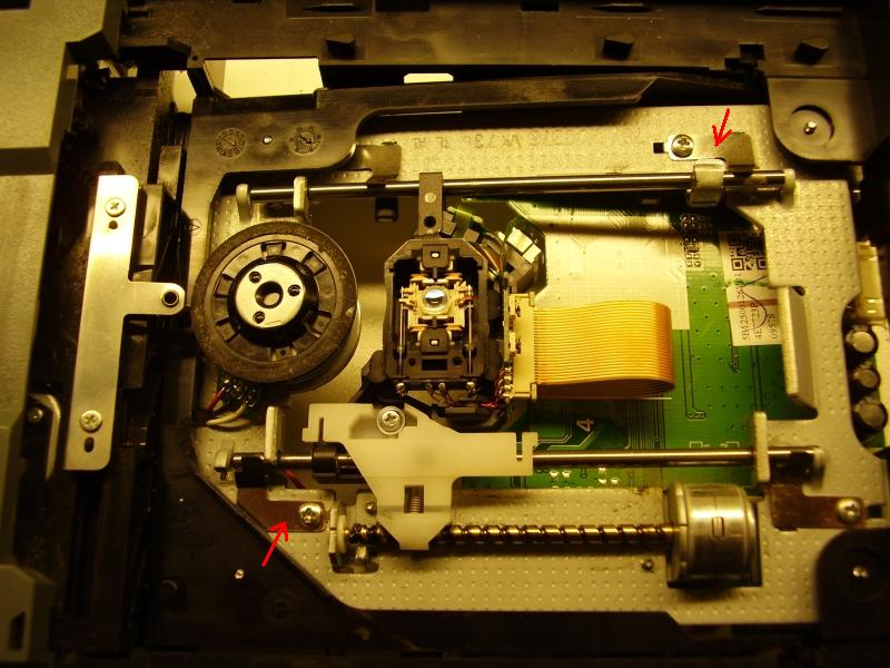
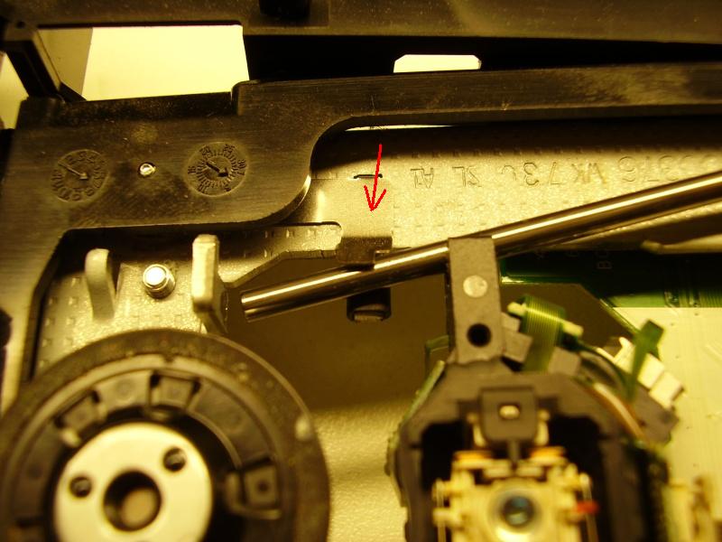
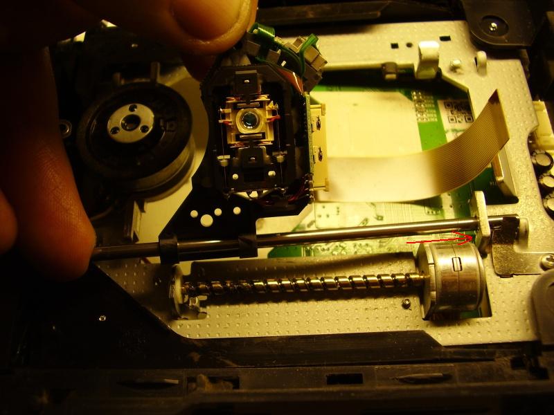
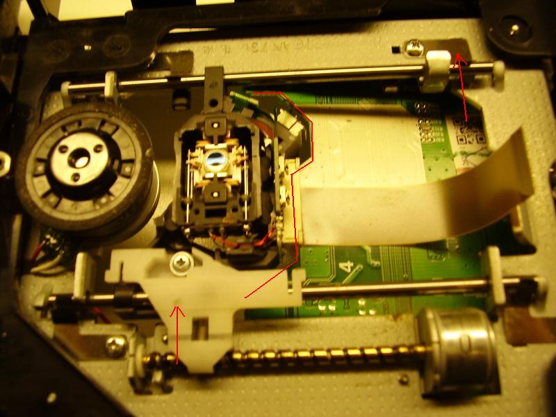
Before we continue its important that the laser unit is now to the left of the pcb(printed circuit board) shown in (step 16) with the red line, so slide the lens unit to the east. Now we can place the back axle back on his final position by hooking it under the metal bracket in the upper right corner and placing back the clamp(Step 16). The lens unit should now slide over the axles, but due the pcb it slides only a few mm to the right and left. Place now back the driving unit by clicking it on the screw axle and screwing it to the lens unit. Connect the flat cable back to the lens unit by opening the clamp (step 17) and insert the cable. Discharge yourself before touching the cable. The flat cable should slide very easy in the connector. Close now the clamps and check of the cable is still inserted far enough.
Now remove carefully the solder clump as show in (step 10) with the soldering iron.
Place back the top and bottom metal case, screw it together with the 4 screws (step1) and you are ready.
Happy gaming.