Esp32 jtag debugger with Sloeber

This is a step by step instruction to setup Sloeber “The Eclipse Arduino Ide” with OpenOcd and a FTDI 2232HL as debugger. With this you can debug your Arduino sketch real time on an Espressif ESP32 in circuit with jtag.

As hardware for the debugger I used 2232HL board from Ali-express , this one was around $14. However every board with a FTDI 2232hl will work.
The 2232HL is a 3.3V device so don’t connect to 5V hardware or else the smoke will escape and the 2232HL will stop working.

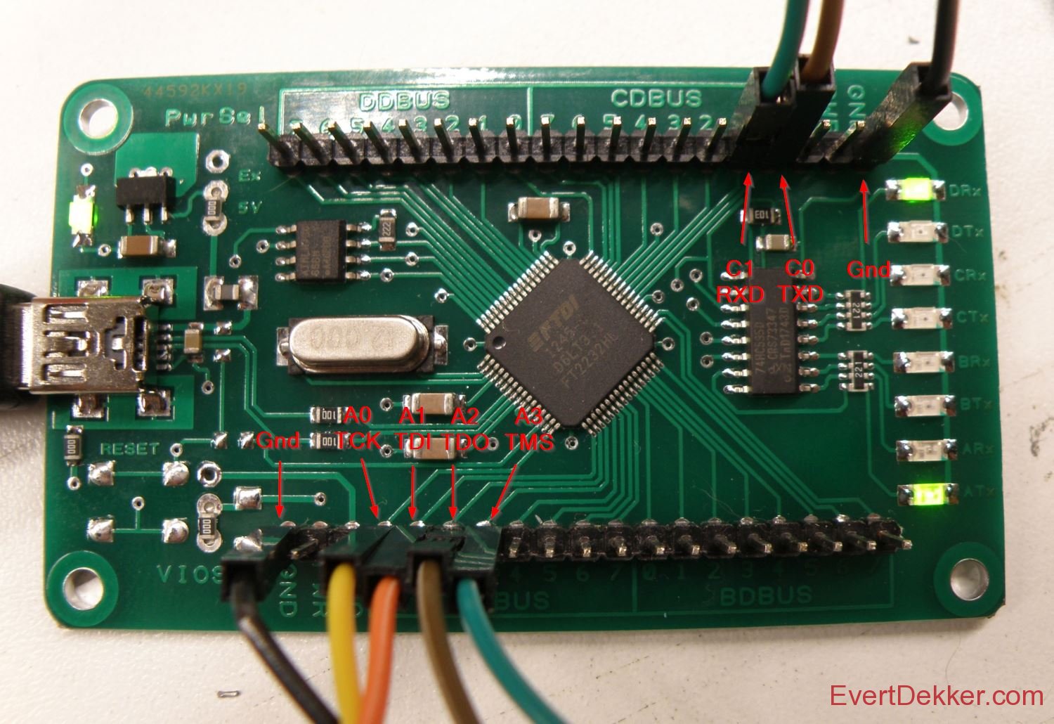
You need to connect it like this to your hardware:
AD0 – TCK (Gpio13)
AD1 – TDI (Gpio12)
AD2 – TDO (Gpio15)
AD3 – TMS (Gpio14)
GND – GND
Optional serial port:
CD0 – TXD (Gpio3)
CD1 – RXD (Gpio1)


Installing Sloeber “The Eclipse Arduino Ide”

  1. Download Sloeber
  2. Extract the gz to the directory of your choice, in this tutorial we use c:\sloeber
  3. Let’s setup some basic stuff for Sloeber.
  4. Arduino -> Preference -> platform and boards
  5. Check Arduino AVR boards and esp8266 2.4.2 (or newer) both are not really necessary for the esp32, but it’s nice to have some samples and libraries.


Installing Esp32 Arduino and Sdk

  1. In Sloeber File -> Import -> Projects from git -> Clone URI and copy the url  https://github.com/espressif/arduino-esp32.git in the URI field.
  2. Press next and uncheck all the branches except master, press next again.
  3. Change the directory to C:\sloeber\arduino-esp32 and press next again.
  4. Choose Import as general project and press next again.
  5. Let’s add it to the ide, Arduino -> Preferences -> Platforms and boards
  6. Press the new button next to the Private hardware path and enter C:\sloeber\arduino-esp32 in the path box.
  7. Press Apply and close
  8. Now we need to download the Esp32 sdk, browse with windows to C:\sloeber\arduino-esp32\tools and click on get.exe
  9. Done


Replace the FTDI by Winusb driver

  1. Download Zadig , no need to install just run it.
  2. Click Options -> List All devices
  3. Choose in the dropdownbox USB <-> Serial Convertor (interface 0).Be careful here that you select the correct device.
  4. Choose the WinUSB (V6.1.xxxx.xxxxx) driver and press the Install driver button
    Note: For some reason sometimes (win update?, other usb port) windows will roll back to the original FTDI driver and you have to do this again.


Installing OpenOcd

  1. Download OpenOcd for the Esp32 from Github (I have used 0.10.0 20180920 version)
  2. Extract the content to C:\Sloeber\Openocd
  3. Download the cfg file for the debugger and place it in C:\sloeber\openocd-esp32\share\openocd\scripts\interface\ftdi
    Note: this file is for the Ftdi 2232HL based debugger that I have. For other debugger look in the C:\sloeber\openocd-esp32\share\openocd\scripts\interface directory. This cfg file can work with other Ftdi based hardware, but I can’t guaranty nor support that.

  4. Connect your debugger to the Esp32 hardware and let’s see if it works by typing on the command line: C:\sloeber\openocd-esp32\bin\openocd.exe –f c:\sloeber\openocd-esp32\share\openocd\scripts\interface\ftdi\quantum.cfg
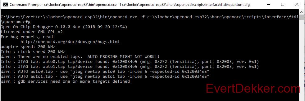
  5. If you get something as in the picture above with the “device found …..Tensilica” in it you rock. The hardware and OpenOcd are working


Setting up a new sketch

  1. Lets start a new project, Arduino -> new sketch, give the project a name and press next
  2. Platform holder c:/sloeber/arduino-esp32 , fill in the rest with the board etc you have. Port is the comport your board is connected to, not the jtag. Press next
  3. Choose Sample sketch -> example -> 01.basics and check blink. Press finish
  4. We need to set some build options for the debugger, right click on your project map, Arduino -> tab compile options and enter in the append to C and C++ field -ggdb -Og. These compiler options are not needed for a production version.
  5. Let’s compile, press Arduino -> verify
  6. And upload it to your board Arduino -> upload sketch. If you have a led connected to the pin as defined in the sketch is should blink now.


Setting up the debugger in Sloeber

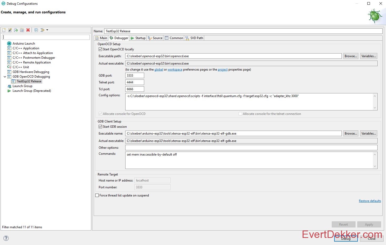
  1. Right click in the project explorer window on your project and choose Debug as -> Debug configurations.
  2. Choose GDB openOCD debugging and add a new configuration by clicking on the + at the left upper corner.
  3. On the debugger tab check Start OpenOCD locally
  4. Executable path will be C:\sloeber\openocd-esp32\bin\openocd.exe
  5. GDB port: 3333
  6. Add to Config options -s C:\sloeber\openocd-esp32\share\openocd\scripts -f interface\ftdi\quantum.cfg -f target\esp32.cfg -c “adapter_khz 3000”
  7. Check Start GDB session
  8. Executable name for the GDB client will be C:\sloeber\arduino-esp32\tools\xtensa-esp32-elf\bin\xtensa-esp32-elf-gdb.exe

  9. Select the Startup tab and set these settings
  10. Check Initial reset, Type: init
  11. In the command box enter:
    target remote:3333
    mon reset halt
    x $a1=0
  12. Uncheck Enable ARM semihosting
  13. Check load symbols, use project binary should be already have your project name
  14. Uncheck Load executable, debug in ram, Pre-run, Set program counter at (hex)
  15. Set the checkbox Set breakpoint at and fill in textbox loop
  16. Check Continue

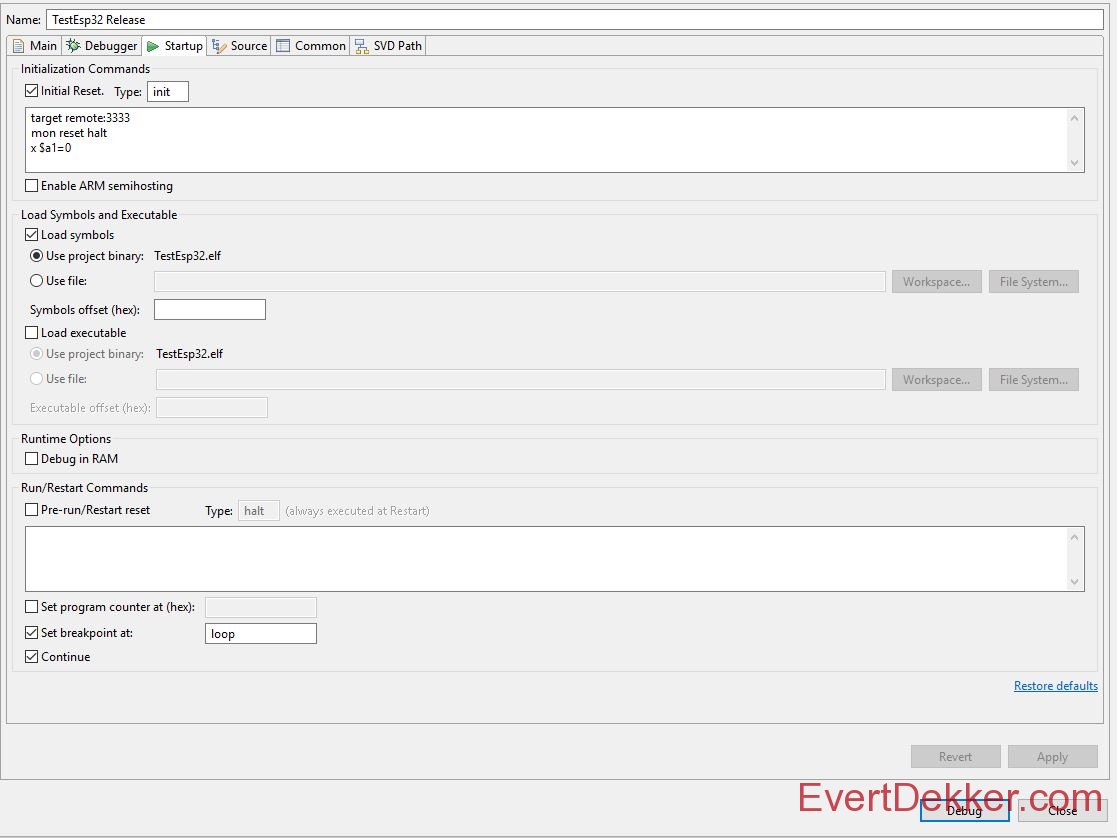
  17. Press the Debug button and there you go

You can also program the ESP32 automatic with the jtag before debugging, add in the command box as described in step 61. below the target remote:3333 line
monitor program_esp32 c:/users/evert/Documents/sloeber-workspace/Testesp32/release/Testesp32.bin 0x10000 verify
Note: It was not possible to use in the command box Eclipse variable like {project_loc}, this would be handy so you don’t have to change every project the hard coded path. These variable like {project_loc} contains backslash “\” and GDB expects forward slash”/”. I did  a lot of Google reading but couldn’t find a solution, if you have one let me know.


How to use it?

It’s a bit out of scope of this tutorial how to describe full the debug function in Sloeber. Because Sloeber is based on Eclipse there is enough videos etc available to help you out.
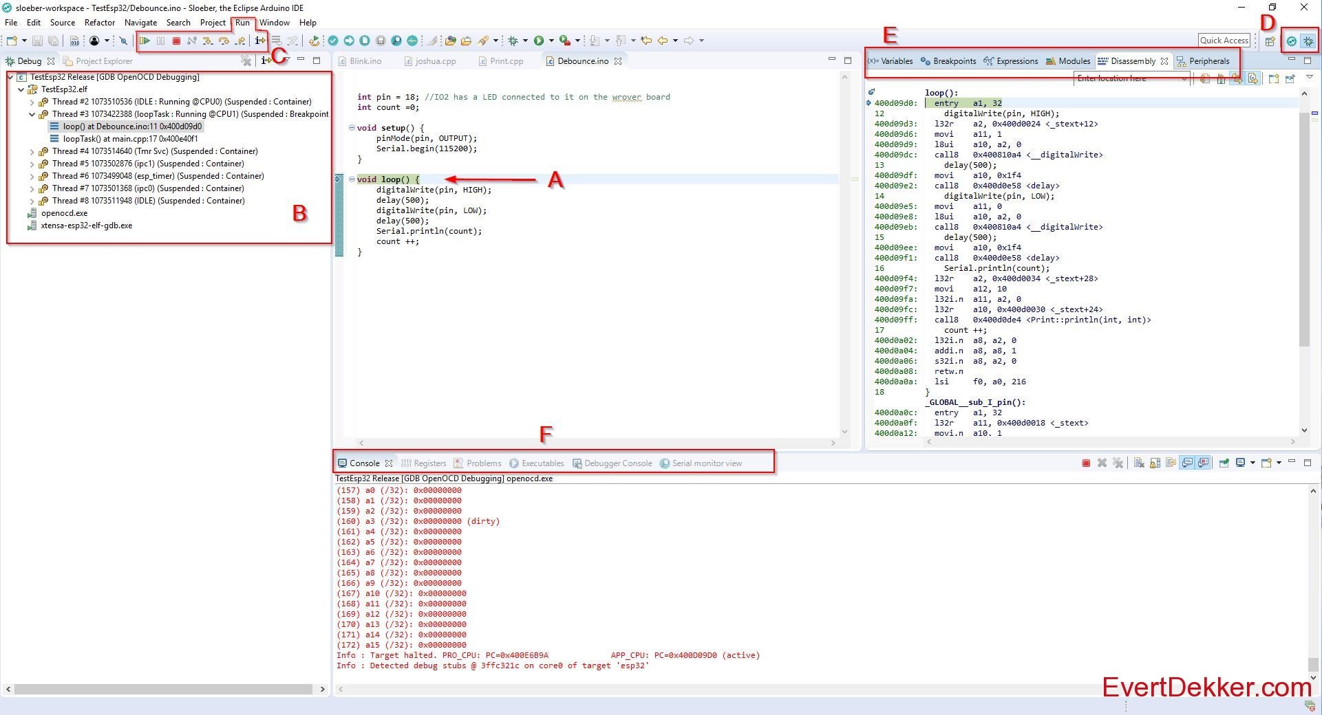
To start a debug session you have to Right click your project -> Debug As -> Debug configuration and press debug. Sloeber will then switch to the debug perspective
As a quick reference have a look at this:

  1. Program code window, program is paused at loop(), this because we set this in step 65.
  2. Thread window, here you can see all the threads that are running on the Esp32.
  3. Control buttons, with these you can start, pause, stop and step in various ways trough your code.
  4. Perspective view, you can switch between code and debug perspective
  5. Various windows to see and influence variable, breakpoints etc. Peripherals is unfortunately not working yet.
  6. Some more windows here, cpu registers and Serial monitor view are the most used.


Note: If you copy the settings direct from this page watch out that punctuation marks  like and are not copied correct (they have an other, wrong ascii value) and will give problems or error’s. Just retype them and it should work fine.

Iot Co2 Sensor

For measuring the air quality in the living room I was looking for a CO2 sensor to build my own CO2 Iot node. Looking around on the internet I found the MH-Z19 sensor, not that expensive and according to other users this sensor is accurate.

A new project was born. The MH-Z19 was combined with a BME280 and TSL2561 so we can measure lux, temperature, humidity, air pressure and CO2 with one Iot node in the living room and send everything over Mqtt to Node-red for further handling and Sqlite database storage.
The biggest part of the design is a copy of my Iot Bme280 sensor module, this Iot sensor runs 40 days on one 18650 li-ion cell. However the MH-Z19 requires 5V and uses a lot more current so I thought it would be nice to power it from a power bank.
The esp8266 requires 3.3V so the 5V from the powerbank is stepped down with a PAM2305AAB330, very interesting stepping regulator that only requires 2 capacitors and 1 inductor. Little bit hard to get here in Europe, but luckily Arrow had “no shipping charge” days and the parts where quick and cheap here.
The MH-Z19 requires serial communication with the esp8266, the last one has power enough to do this with a software uart. Example for the Arduino IDE to get data out of the MH-Z19 was also quickly found. With all of this together the data was quickly streamed to the Mqtt broker.
The pcb was designed so that it will fit inside a Hammond 1591 case and the pcb is used like a sort of front panel this way. The MH-Z19 is milled out the pcb so you can mount it on the back.


Schematic
Pcb bare front
Pcb bare back
Pcb finished front
Pcb finished front detail
Pcb finished back
PlayPause
previous arrow
next arrow
 
Schematic
Pcb bare front
Pcb bare back
Pcb finished front
Pcb finished front detail
Pcb finished back
previous arrow
next arrow


If want to make your own, or use some parts from the design, here are the Altium 16 design files.

1622 Downloads

Iot light switch with mains input

IOT light switch with input for switch with mains.

The idea is the same as the famous Sonoff wifi switch but this one has also an input for a 230V~ switch so you can still use your existing light switches.
Most of the light in my house is replaced with Sonoff touch switch , however this is not possible everywhere. For example on the stair case we have what’s called a switching circuit (wisselschakelaar for the dutch readers) and due to the wiring it was not possible to replace them both with a Sonoff touch switch.

To detect the present of the mains on the input I started with a simple schematic based around the H11AA1 which you can find a lot on the net as mains or zero cross detector for Arduino. This worked flawless, see the photo of my experiment. With the CTR (current transfer ratio) of 20% it was necessary to have a current of at least 3.3mA through the led of the opto-coupler. With the used current limiter resistors of 2x33K this will dissipate 0.71W.
Not that much energy to “waste”, however depending on the state of the switching circuit and the Mqtt state this “wasting” can occur 24 hours a day, this can be done better.
Searching for an opto-coupler with a higher CTR should do the trick. The SFH6286-3 has a CTR of 100~320%, a led current of 1mA would be enough with this CTR ratio.  2x110K Resistor will limit the current to 1mA and will dissipate 0.22W.
That’s 0.5W less then before, that will save 4.36kWh per year maximum.

Note: All calculation done in this post where done for 230V~ 50Hz.

The rest of the circuit is not that special. The Esp-01 is programmed with an external programmer and then equiped with a OTA bootloader so programming is only needed to be done once (theoretically). To have enough room for the OTA bootloader and the sketch I have updated the memory from the esp-01 from 1MB to 4MB. That’s easy done with a hot air gun to replace the memory chip. 4Mb spi flash chips can be bought very cheap on ebay.
The solid state relay will consume 6mA at 3.3V, this is broad within the max pin GPIO current of the ESP8266 so no transistor driver is needed.

Because the Esp-01 doesn’t have that much IO pins available the RX and TX can also made be available as IO, to disconnect them from the uart use:

pinMode(1, FUNCTION_3); //GPIO 1 (TX) swap the pin to a GPIO.
pinMode(3, FUNCTION_3); //GPIO 3 (RX) swap the pin to a GPIO.

You can still use the TX/RX pin to program the ESP-01, but using them in your sketch is not possible anymore. To still have the possibility to debug I use a remote debug library to debug over telnet.

Schematic
Bare pcb
Finished pcb
Test setup
Experiment with the optocoupler
Current trought the optocoupler
Scoop 1
Scoop 2
Pcb build in the lamp
PlayPause
previous arrow
next arrow
 
Schematic
Bare pcb
Finished pcb
Test setup
Experiment with the optocoupler
Current trought the optocoupler
Scoop 1
Scoop 2
Pcb build in the lamp
previous arrow
next arrow


If you want to make your own, or use parts of the design here are  the Altium Designer 16 files:

1526 Downloads

Esp-01 Programmer Mod

For a small project of my there was needed a programmer for the Esp-01 wifi module to program the module. It’s not really a programmer, but more an usb to serial convertor.
Simple search on Aliexpress gave a nice looking programmer that you can stick in your pc and voila Esp-01 can be programmed, can be bought for $0.78 including shipping.

Bummer, when it arrived and want to use it to program the Esp-01 module it wasn’t possible to get it working with the Arduino ide. The ide was constant coming with the error espcomm sync failed and other com port related errors.
After a quick google search it was clear, the bought Esp-01 programmer works fine out of the box when you use the Esp-01 with the AT commands, but for using it with the Arduino Ide the Esp-01 module had to be set first in programming mode by connection GPIO-0 to ground and reset the module to bring it in flash uart download mode.
Most of the solutions found on the net uses 1 or 2 buttons to get this accomplished, but I wanted automatic programming mode just like the NodeMCU does. Just press upload in the Arduino ide and go….

The programmer uses the same usb to serial convertor (CH340G) as used in the NodeMCU so it should be possible to use the same schematic. The Arduino Ide already supports the NodeMCU so no need to change drivers, board.txt or platform.txt files.
The part that’s responsible for pulling GPIO-0 low and resetting the Esp-8266 is only two general purpose npn transitors and 2 resistors.

So I added 2x BC547 (or use any other general purpose transistor) and 12K resistors to the bottom of the programmer board. It’s not my best soldering work, but it will do the job.

Soldered 2 wires to pin 13 and 14 of the CH340G and connected them to the transistors on the other side.
You can fix everything with some hotglue if you want.

Change in the Arduino ide the setting Tools , Reset Methode to NodeMCU and you are ready to go.
Every time you press now upload the Esp-01 will be set in serial download mode and you can upload you fresh developed code.


Happy programming.


Iot SensorV2 with battery onboard

Not a complete new design, but a redesign of my Iot Esp8266 sensor V2, the schematic is exact the same however this time with a on board 18650 3.7V Li-ion battery.

The Iot sensor node will measure temperature, humidity, atmospheric pressure and light. The light is measured with the TSL2561 and temperature, humidity, atmospheric pressure with the Bosch BME280.

In the previous design the battery was placed in a separate battery holder and the pcb was taped to the battery, not really the ideal solution.  So the idea was born to combine everything on 1 pcb.
The first idea was to place the battery beside the electronics, when this was finished I thought that can be smaller and made also a design where the pcb is on top of the battery. Still I couldn’t decide if I wanted the side or top version. Ok, lets combine both designs and we will see later what’s version is nicer.
Just as mentioned in then previous design, it’s very hard to solder the BM280. My opinion is that you only can solder it good if you use a stencil to apply the solder paste and place the pcb in the oven or use a hot air station.
For the battery clips I used the Keystone 16~19mm PC Battery clip.  In the datasheet they note that for an 18650 with build in protection circuit you need 48mm between the front solder pins, that will make it fit for battery’s of 68mm if you add the rest of the clip. However I don’t think this is correct, at least not in my case. 18650 battery with build in protection are 69,7 mm long, it will fit but it looks that it’s way to tight. For 18650 battery with flat head the clips are to far apart and won’t make contact. An 18650 with button head will fit perfect. If you want to make your own sensor node, keep in mind that there are a lot of different sizes 18650.
I’m using now the Sanyo NCR18650GA 3350mAh – 10A Button Top and that fits perfect, they are 66.7mm long (battery used on the photo’s is not the Sanyo).

3d design in Altium
Pcb and stencil
Finished board
Board on top of the battery
Board on top of the battery top view
Board with battery on the side
PlayPause
previous arrow
next arrow
 
3d design in Altium
Pcb and stencil
Finished board
Board on top of the battery
Board on top of the battery top view
Board with battery on the side
previous arrow
next arrow


You can find a test/demo Arduino program on my Github.


If you want to make your own, or use parts of the design here are  the Altium Designer 16 files:

1651 Downloads