Iot LightSensor Node
It is some time ago, but finally a new project from me.
The idea was to make an light sensor for my domotica that will communicate with my Mosquitto Mqtt broker over wifi, the old light sensor was cast in epoxy but due the weather the epoxy got discolored and is not working therefore anymore accurate. And with accurate I meant not at all anymore. The TSL2561 was very interesting to use as sensor. There are some nice Arduino library’s that are very complete.
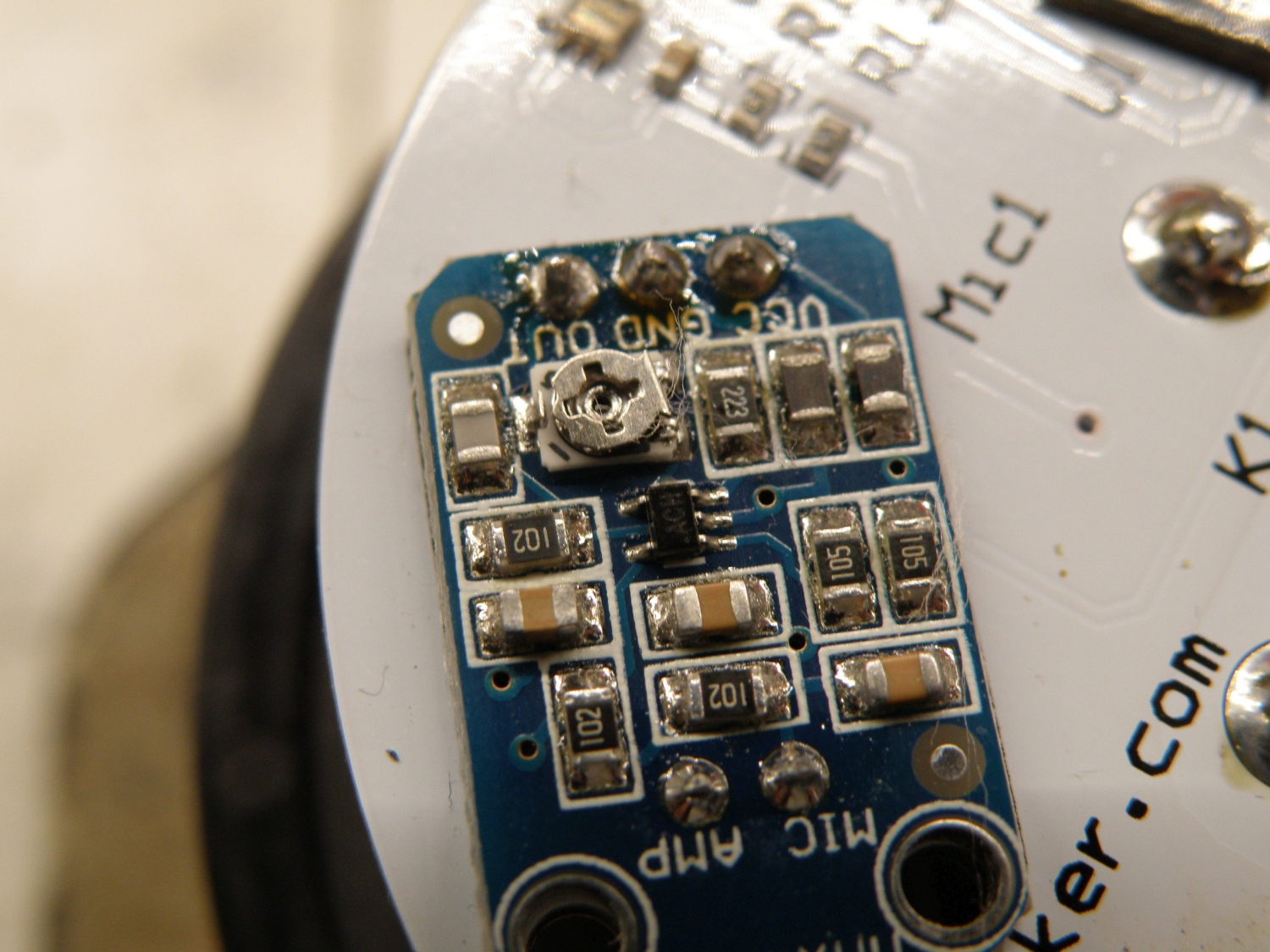
During design there was also a temperature sensor (DS1820) and decibel meter (MAX4466 module) added. Don’t know if the decibel meter will be accurate, but it’s just for logging the airplanes flying over my house. The decibel meter will later be calibrated with an real decibel meter, we will see how accurate this is.
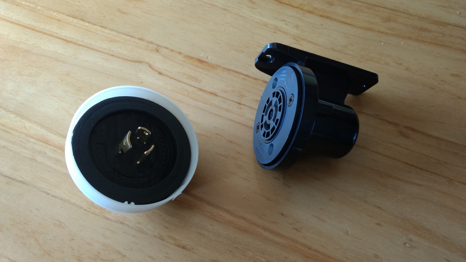
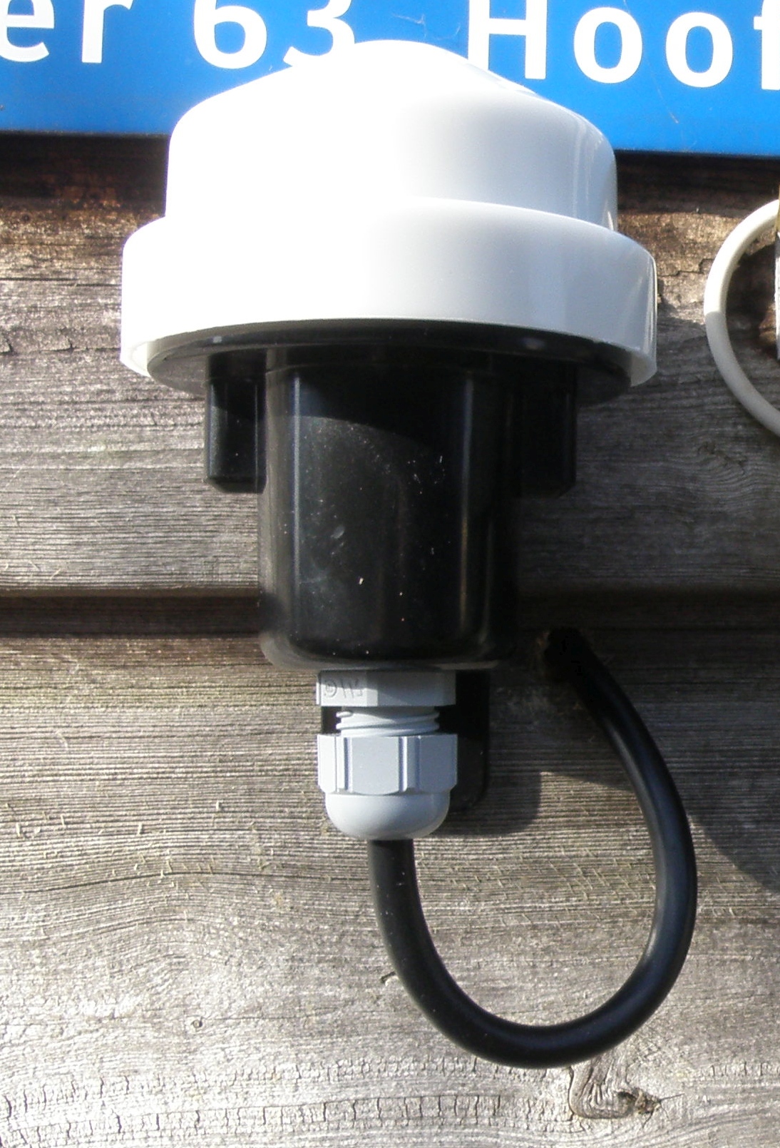
The design started with finding a suitable enclosure, water resistant and suitable for measuring light. On ebay I found a nice one and not that expensive $8,00
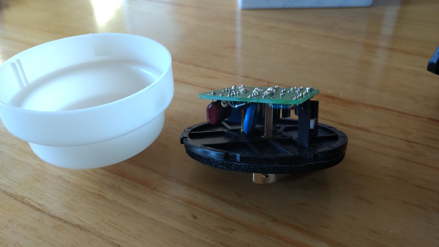
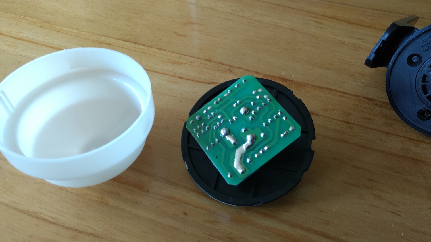
When the sensor was in I first took it apart and see what the possibilities are with the enclosure.
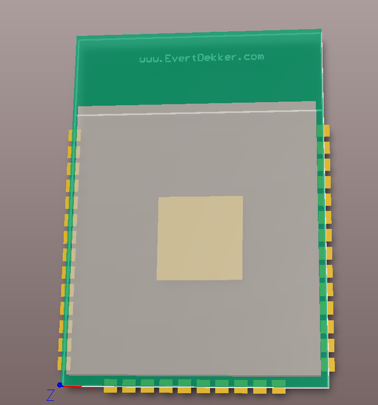
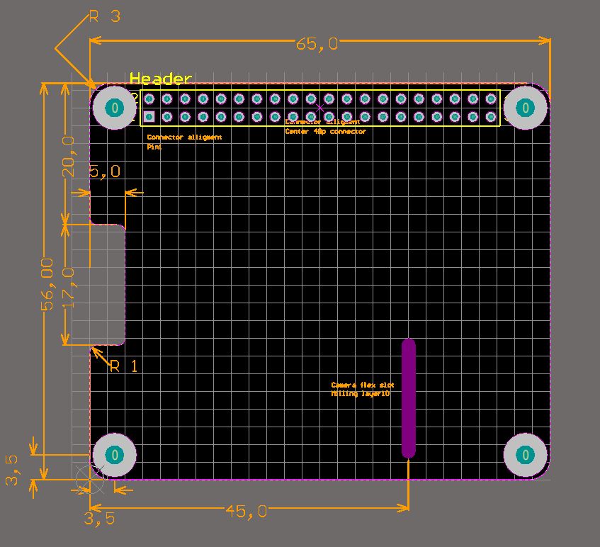
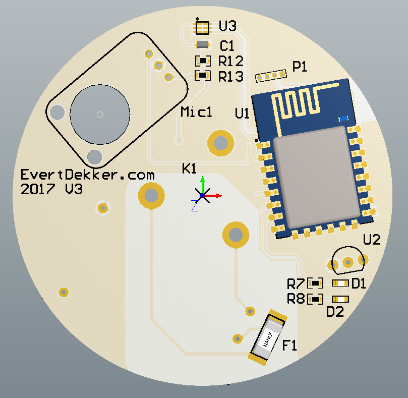
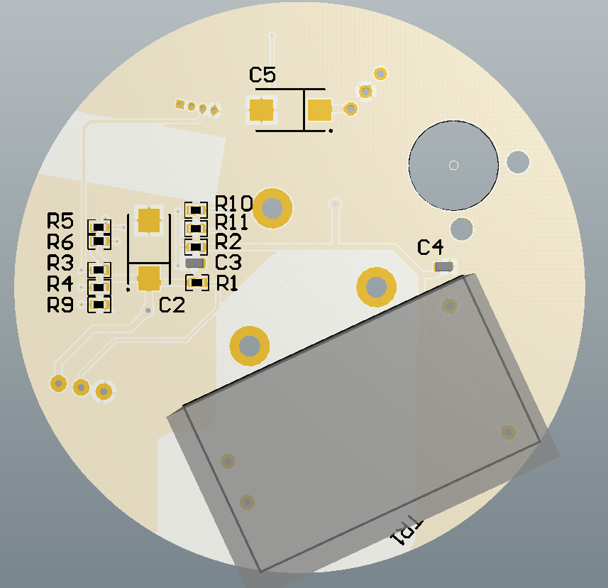
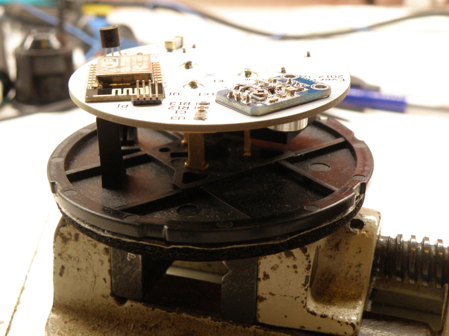
A round pcb with a diameter of 63mm was needed. I want to design the board with Altium Designer to get more familiar with this pcb design software. Easier said then done.
It’s my 4e design with Altium, but because of the round pcb and the strange angles that some of the components must placed it took some time to get it all finished. But it was all very educational.
The first ideas was to use the new ESP32 module, would be nice to use this very powerful mcu in the design, but there was no room enough. Next time if there’s not enough room I will not use the ESP32 module, but just the ESP32 mcu. Due the connector in the center of the pcb with it’s mounted to the enclosure there was not that much space as it looks like. Because of the limited usable space i used the good old EPS8266 module, the Esp-12.
Pcb is ordered, story will be continued.
Update 11/03/2018:
It took some time to finish this project. Due some stupid and unseen design faults I had to redesign the pcb 2 times.
In V1 I was completely forgotten that the ESP8266 has an AD convertor with a max input of 1V and the microphone amplifier was spitting out Vcc and that’s is 3.3V.
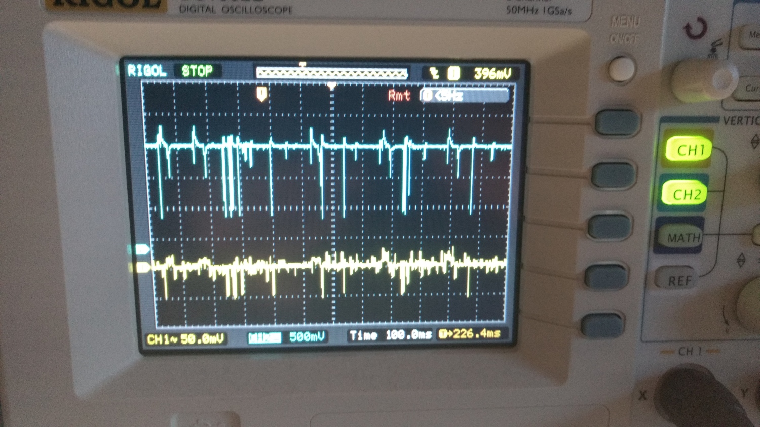
After adding a voltage divider in V2 the mic amplifier was sensitive to the noise on the Vcc rail and added a lot of switching noise to the output of the amplifier.
In V3 there was a lowpas filter added in the power supply line to the mic amplifier and that did the job, smooth about from the amplifier.
Still not all problems solved, the mic amplifier didn’t amplified enough and after some testing I noticed that in the original design from Adafruit they used an 100K pot meter and my amplifier from Ebay had a 10K resistor. After replacing that everything worked fine and the data is coming in nice. Except the temperatuur sensor, because it’s inside the enclosure it doesn’t measure accurate.
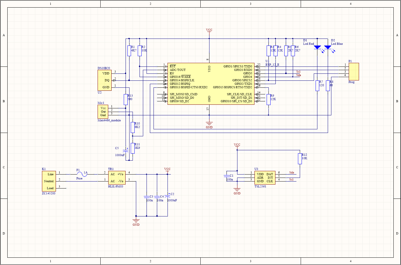

If you want to make your own, or use some parts. Altium 16 Schematic and pcb files.