Led Cube 5x5x5 RGB

Not a design from me, but a kit that I bought on the internet. Looked fun to me to build one, but you can forget the “fun” word very fast. What a hell of a job to soldering all the leds to the wires.
According the manual it was for an experience solderer 3 hours work. I can say I’m very experience, but it took me 9 hours.
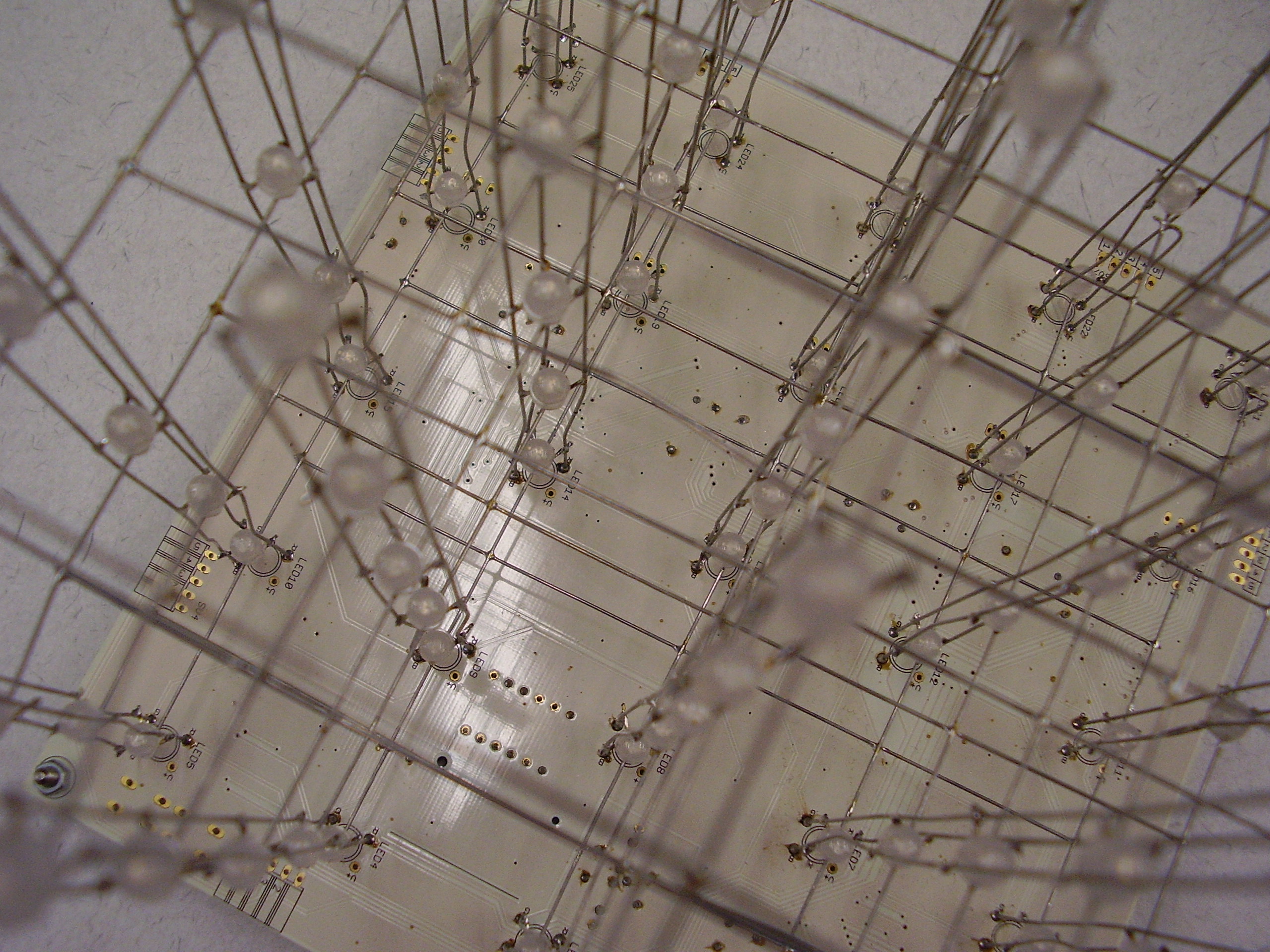
Straighten all the wires was already a lot of work, after that you need to solder 5x5x5x4=500 pins from the leds to the wires.
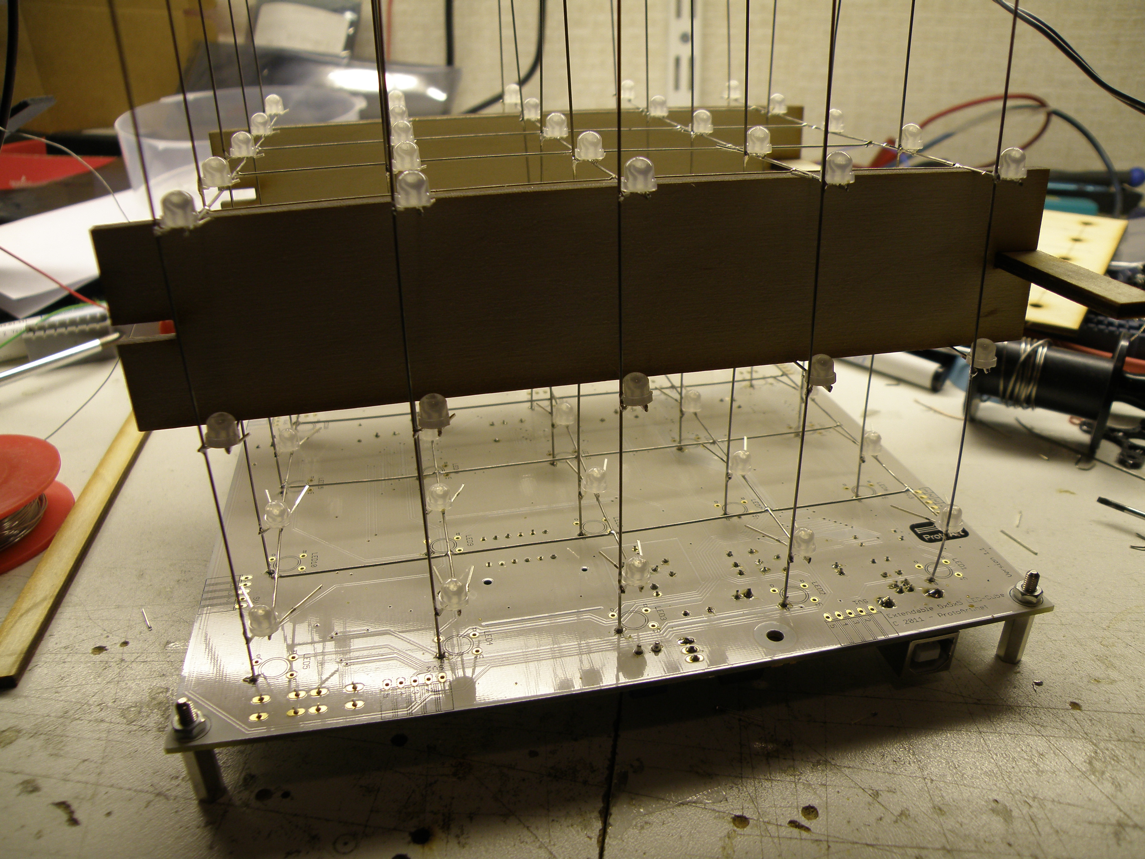
The first step was making the layers. For this they provided a die where you put the leds upside down in and then solder the common frame to all the leds in a matrix.
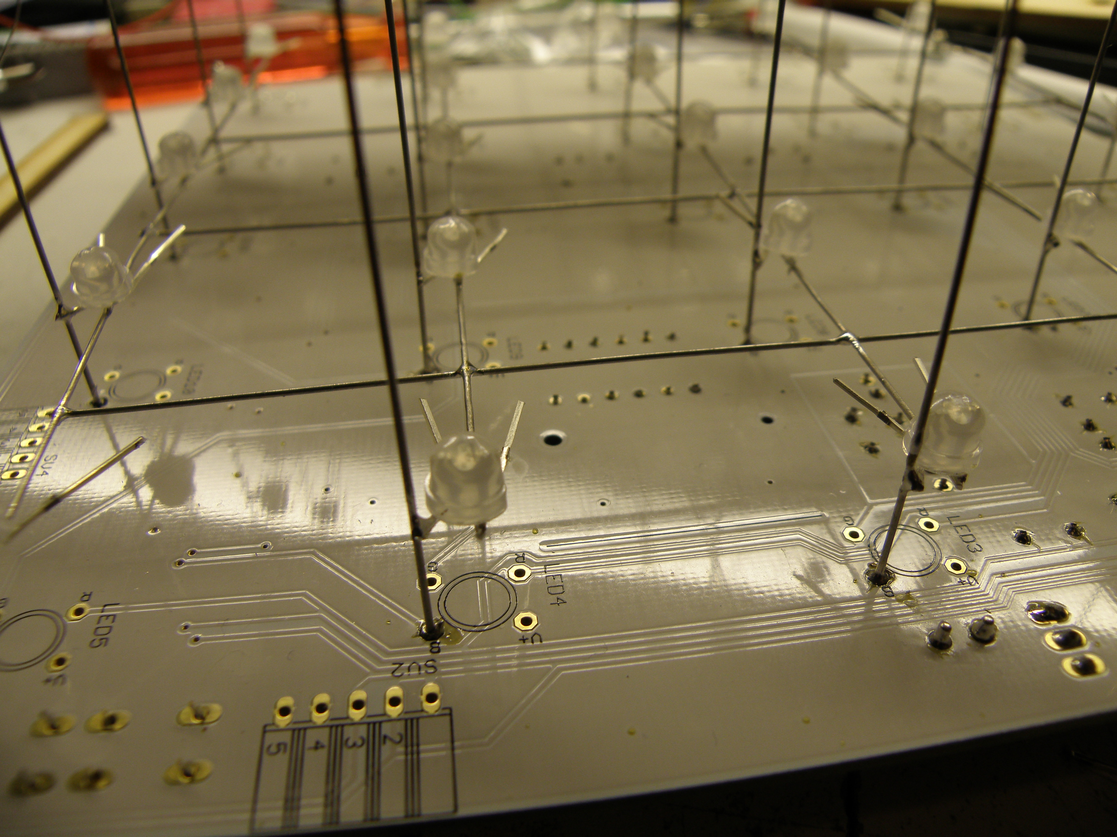
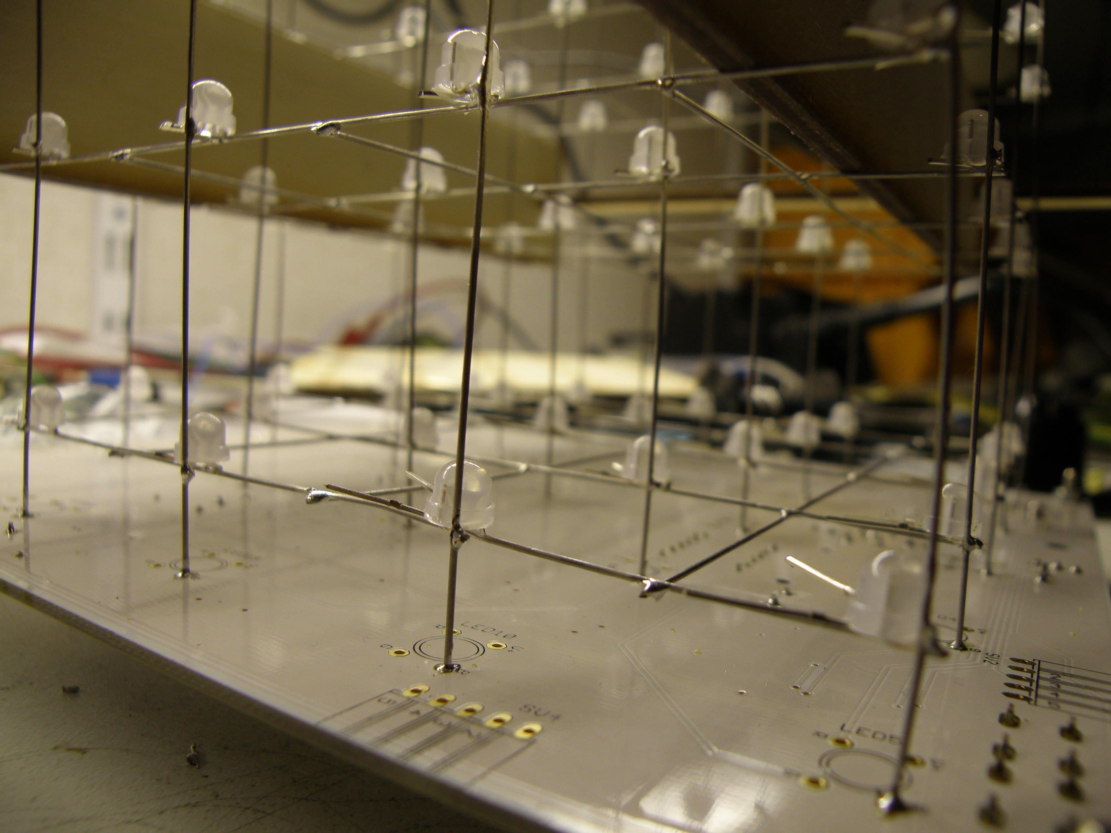
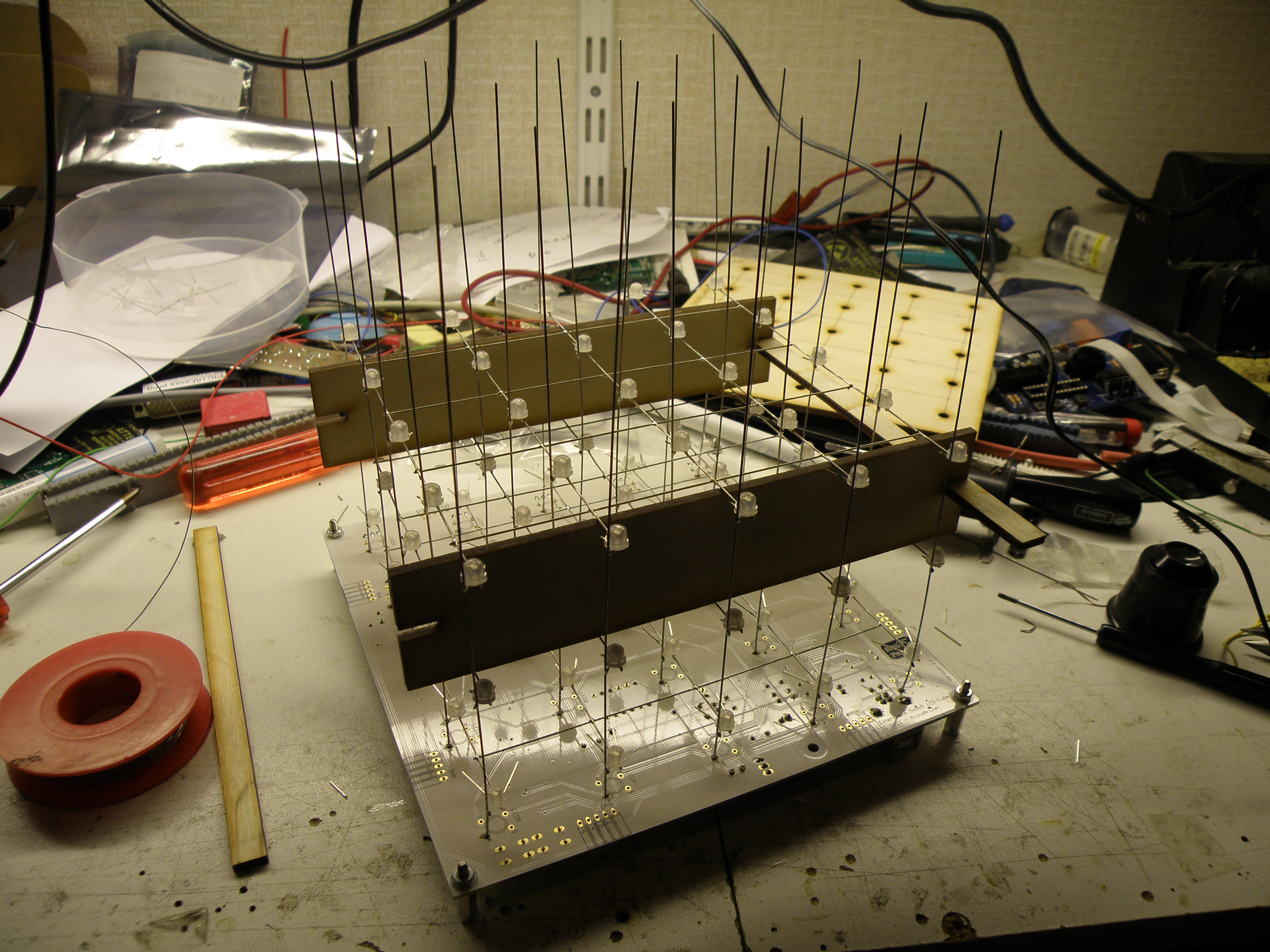
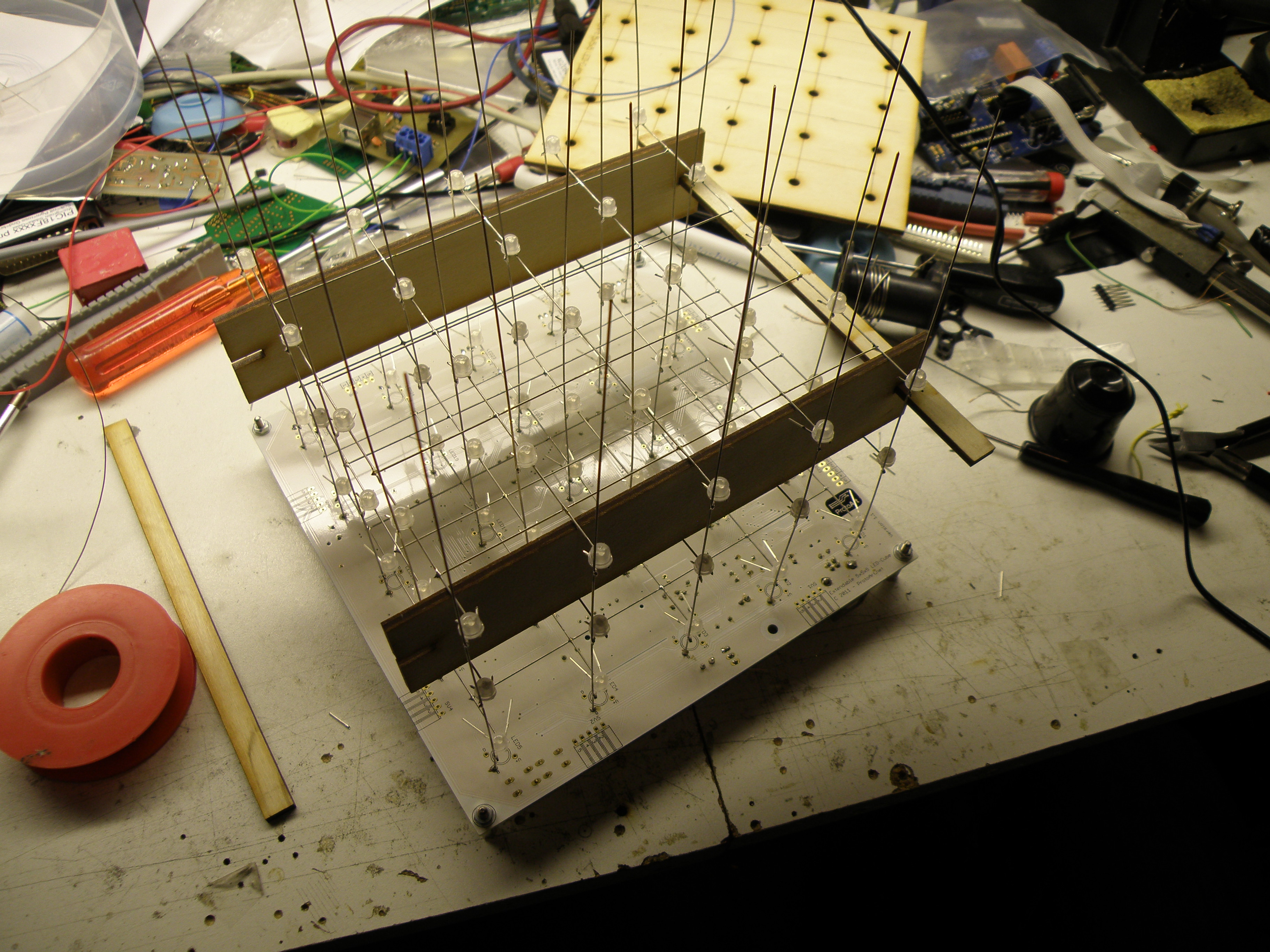
In the second step you needed to solder the vertical wires on the pcb and lower the layers from step 1 over it, holding it at the correct distance with the provided spacer and soldering the RGB pins from the leds to the wires. Repeat this for the other 4 layers.
The problem with this was if you didn’t bend the led pins precise in step one the led pin was not close enough to the vertical wire what made it difficult to soldering it. Bending the led pins a bit was not difficult for the leds on the edge, but the leds in the middle was hard to reach.
Finale finished with the soldering work and after uploading the test program to it…. 4 leds dead, and 3 not at the edge but in the middle.
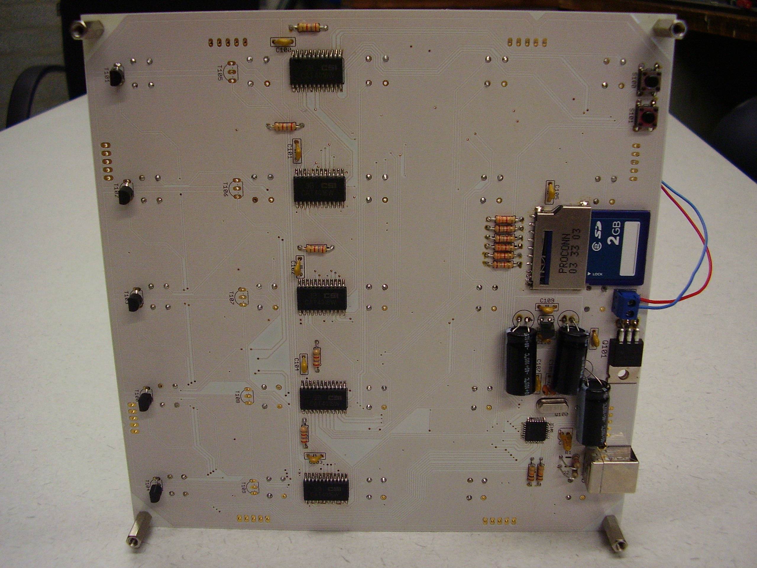
Very hard to get to the leds and replace them. During testing I blew up 1 of the drivers (CAT4016W)  due difference in ground potential from my soldering iron. After replacing the driver everything was working fine finally.

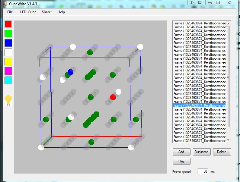
With the provide PC tool you can make your own sequence and upload it to the sd card in the cube.

But, not all the troubles where over now. I did bring it to my work to show it to my colleagues and one of them dropped the cube on the floor with the result is was completely bend. Did bend it a bit back but was to anxiously that it could brake. See the result in the Finished picture, this is the result after the drop, befor it was nice straight.
After this disaster the next one was there, somebody used my power supply for other purposes and set it to 12V. I didn’t checked it and switch it on with the result that all the drivers where fried. Back to the soldering iron again to replace them all.


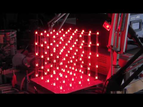
Small impression of making the cube and the result.

Cubetool
PlayPause
previous arrow
next arrow
 
Cubetool
previous arrow
next arrow

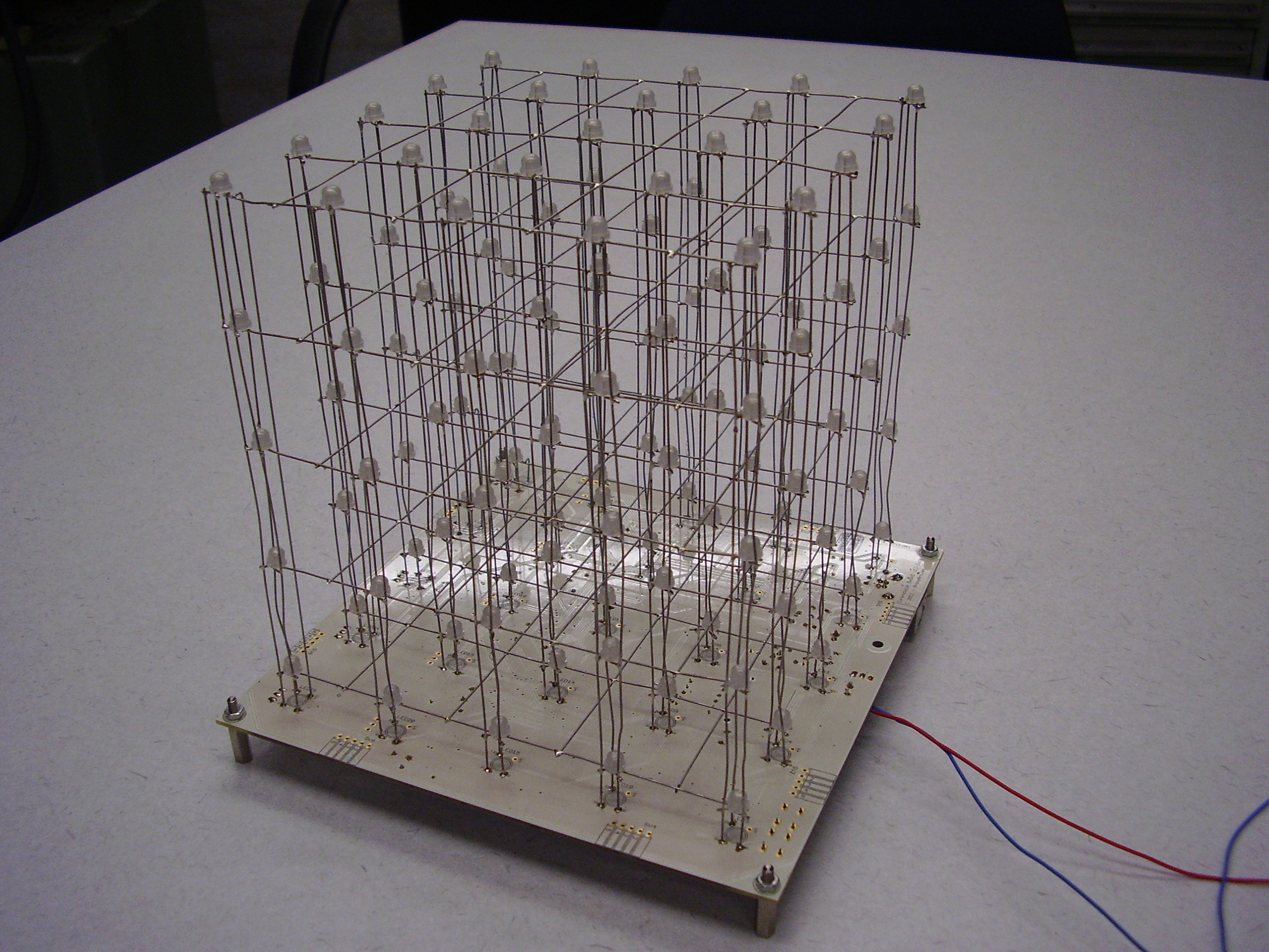
The cube in action. Due the multiplexing of the layers and the camera shutter it flickers a bit, but in real it doesn’t.

5x5x5 RGB Led cube


Nixie Clock #2 IN16

My second nixie clock design.
This clock is compared with my other Nixie clock much simpler, it uses less components and the code is kept simple and short.
The segments are multiplexed to increase lifetime of the tubes and simplify the 170V power supply.
Due the separate tube pcb it’s possible to use it with other tube’s. I have used IN-16 tubes for this clock, bought them on ebay.

To-do: Wooden enclosure with aluminum top and bottom.

Schematic
3D Design Front
3D Design Back
Finished top pcb
Finished bottom pcb
Finished tube pcb
It's working
Result2
PlayPause
previous arrow
next arrow
 
Schematic
3D Design Front
3D Design Back
Finished top pcb
Finished bottom pcb
Finished tube pcb
It's working
Result2
previous arrow
next arrow

The clock in action.

Multiplexing in action, shot with 1000fps camera


'============================================================================

'=  Simple IN-16 nixie tube clock with multiplexed segments, low part count =
'=             Shortest Nixie Bascom code available on the net              =
'=                                                                          =
'=                    Copyright Evertdekker.com 2011                        =
'=                    Code Created with Bascom 2.0.7.1                      =
'============================================================================

$regfile = "M88pdef.dat"
$crystal = 1000000                                          'Internal 8mhz div/8
$hwstack = 32
$swstack = 64
$framesize = 16

Config Clock = Soft                                         'Use the softclock, 32.768KHz crystal connected to tosc1/2
Config Date = Dmy , Separator = -
Enable Interrupts
Date$ = "15-03-11"
Time$ = "12:15:45"

'== Setup hardware ==
Digit Alias Portc
Config Digit = Output                                       'Set up portc as output for the digit
Ddrd = &B00111111                                           'Setup portd as output for the segment and keep bit6&7 free for other use
Button_hr Alias Pinb.0
Button_min Alias Pinb.1
Config Button_hr = Input
Config Button_min = Input                                   'Set buttons as input
Set Portb.0
Set Portb.1                                                 'Switch on the pullup for the buttons

Dim Multiplex As Byte
Multiplex = 1                                               'Multiplexer starts with 1

Do

Select Case Multiplex
 Case 1 : Digit = _sec Mod 10                               'Seconds
 Case 2 : Digit = _sec / 10                                 'Seconds tens
 Case 4 : Digit = _min Mod 10                               'Minute
 Case 8 : Digit = _min / 10                                 'Minute tens
 Case 16 : Digit = _hour Mod 10                             'Hour
 Case 32 : Digit = _hour / 10                               'Hour tens
End Select

Portd = &B11000000 Or Multiplex                             'Switch on one tube
Waitms 2                                                    'Some delay to slow down the multiplexer

If Multiplex < 32 Then                                      'Shift the multiplexer one bit to the left until all 6 segments are done
 Shift Multiplex , Left , 1
Else
 Multiplex = 1                                              'Start over again at segment 1
End If

Debounce Button_min , 0 , Setminute , Sub                   'One of the buttons pressed, jump to the sub to change the time
Debounce Button_hr , 0 , Sethour , Sub

Loop
End

'=== Subs ===
Setminute:
 Incr _min
 If _min > 59 Then _min = 0
Return

Sethour:
 Incr _hour
 If _hour > 23 Then _hour = 0
Return


Talking dice

A long time ago when i started with electronics one of my first projects was a talkingdice from the Elektor magazine November 1982.
It was based on the Texas instruments TMS5100 speech chip. The eprom was programmed with dutch speech code and it was working reasonably, considering the year (1982) it was not bad at all.
It could only speak from 1 to 6 with no visual feedback.
After all these years Elektor has never made a modern version of the talking dice and it looks fun to me to make a new dice and send it to Elektor for publishing in there magazine, but after keeping me warm for 2 years they decided not to publish it anymore.
Now it’s on my own website that has more readers then Elektor these days Smile

This talkingdice is based on my RC2 decoder / soundplayback and will produce much better sound-quality with visual feedback and the option to throw with 1 or 2 dices.
You can choose between 1 or 2 dices by keeping de roll button pressed during start-up.
For the enclosure i have used a transparent Straapubox red (Conrad 528347). It gives a nice finish and make the leds better visible.They are also available in other colors, so let your creative flow.
The current through the leds is limited to 8mA to extended battery life time and prevent that the maximum source current of the M88 will be exceeded.

Schematic
Sprekendedobbelsteen Elektuur 1982
Talking Dice
Dice open enclosure
Finished Dice
Finished Dice
PlayPause
previous arrow
next arrow
 
Schematic
Sprekendedobbelsteen Elektuur 1982
Talking Dice
Dice open enclosure
Finished Dice
Finished Dice
previous arrow
next arrow


Download here your stuff if you want to make one yourself.
Eagle cadsoft pcb &amp; schematic
Hexfiles ready to run
Source code written with Bascom-Avr
Voicefiles

If you want to do more, for example make you own voice files with your own voice, read this and  specially the RC2-Howto.pdf in this download.

Rs-485 Hub Smd


My old Rs-485 hub was getting to small to connect all the device from my Joshua domotica.
Designed a new one with smd components to reduce the size.
The line drivers SN75176 are still dip-8 to change them easy when there’s one broken, not that they ever breakdown (last 10 years zero) but you never know.
It’s stack able for extending the ports.


Schematic
3D Design
Finished
Finished
PlayPause
previous arrow
next arrow
 
Schematic
3D Design
Finished
Finished
previous arrow
next arrow


Download schematic and Eagle pcb files:

2369 Downloads

Video Splitter Amplifier

A simple analog 75Ω video splitter amplifier based on the NE592.
What can you tell about this? Not much. I needed a video signal splitter to get the signal from the security cams to the recorder, web server and monitor.
It splits 1 input to 3 outputs.
I made it stackable so that you need only 1 power supply, thus the stack passes only the supply no video.

In this design the gain is determined by R5 3K3, however for some cameras the gain was to high and I replaced R5 with a 25K trim pot meter so you can adjust the gain.

Schematic
3D Design
Finished
Stacked
Stacked
PlayPause
previous arrow
next arrow
 
Schematic
3D Design
Finished
Stacked
Stacked
previous arrow
next arrow


If you want to make one yourself, contact me for the pcb or download the Eagle-cad files here.

1501 Downloads