Dwin Hmi display piggyback
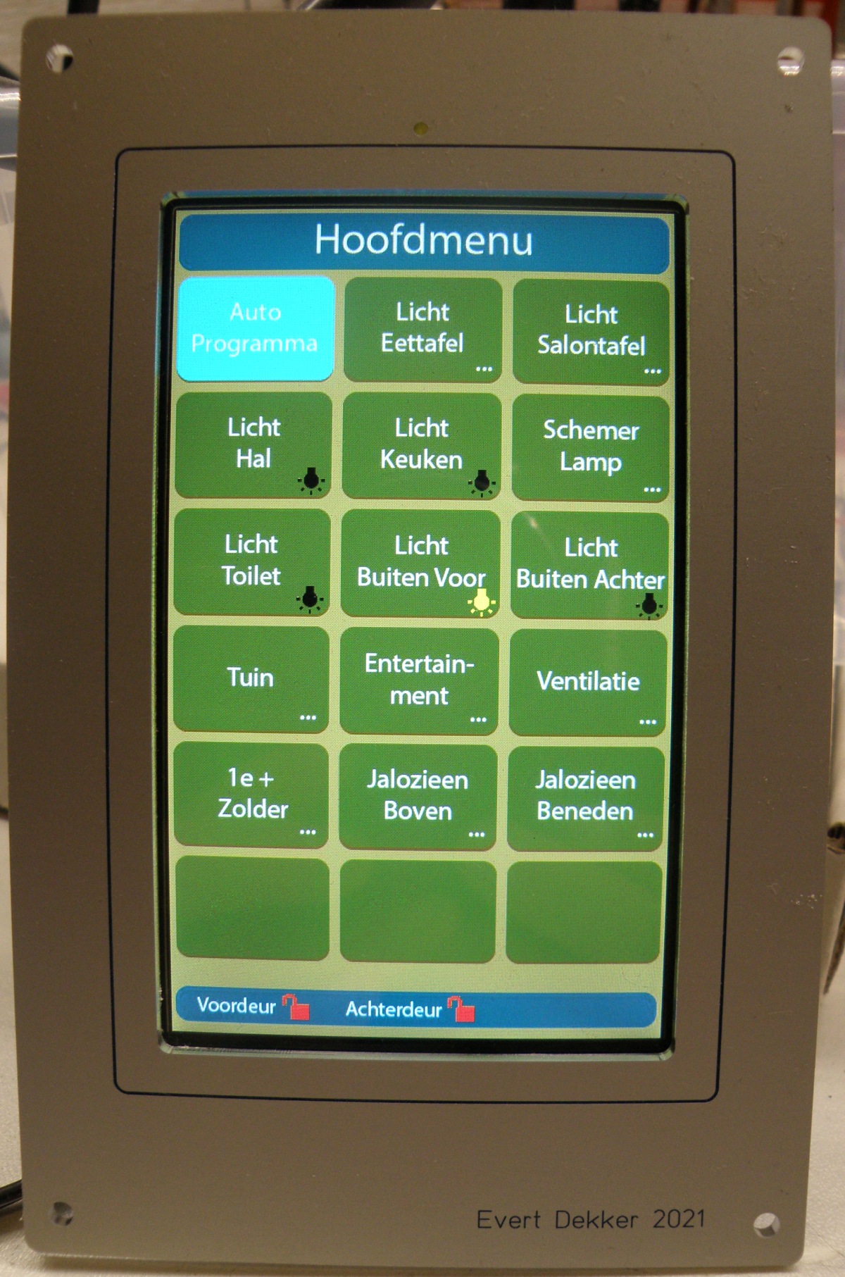
My touch panel for the Joshua domotica in the kitchen needed an upgrade. The old touch display used the Rs485 wired network and was not capable of communicating with a Mqtt broker.
Looking at various brand Hmi (Human Machine Interface) touch display my choice was made for a display from Dwin. The popular Nextion display is nice to work with, but did not meet all my requirement ‘s. I wanted capacitive touch, higher resolution and a buzzer for feedback.
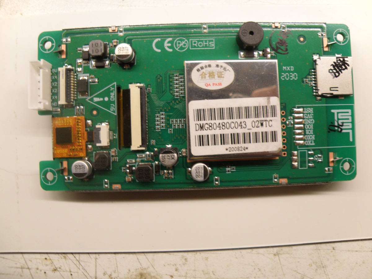
The Dwin display was purchased from Ali express for a very sharp price and the one I picked was the DMG80480C043, paid around €15 for it.
A 4.3” display with a resolution of 800×480, capacitive touch, buzzer and for communication with the world a serial port.
You can program the display with the free Dgus software. I recommend to stay for now to the V7 version, the V8 is still to unstable.
Holly cow, what is this all very bad documented by Dwin it took me along time to get the software under control and understand why it works and why it sometimes not works what you want to accomplice. Learned the most from a Russian forum that could I could read with the help of chrome translation.
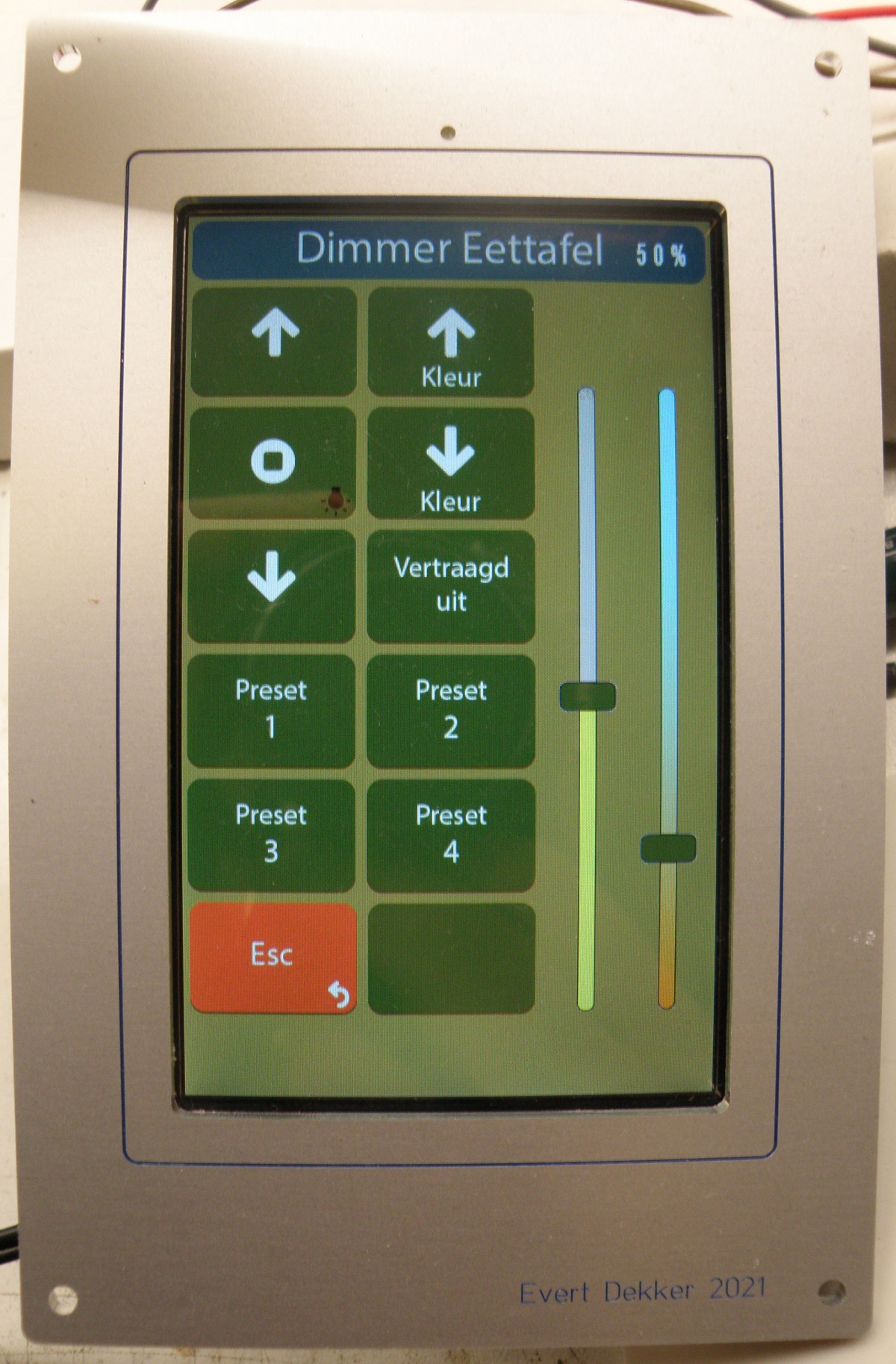
All the display pages where designed with Adobe Illustrator. For every position of the slider (100!) a separate image. It’s possible in the Dgus software to move only the nob in software, this was much easier to do, but I liked that the background of the slider also change in color. Same for the color temperature slider, it will change between blue and orange depending of the kelvin value.
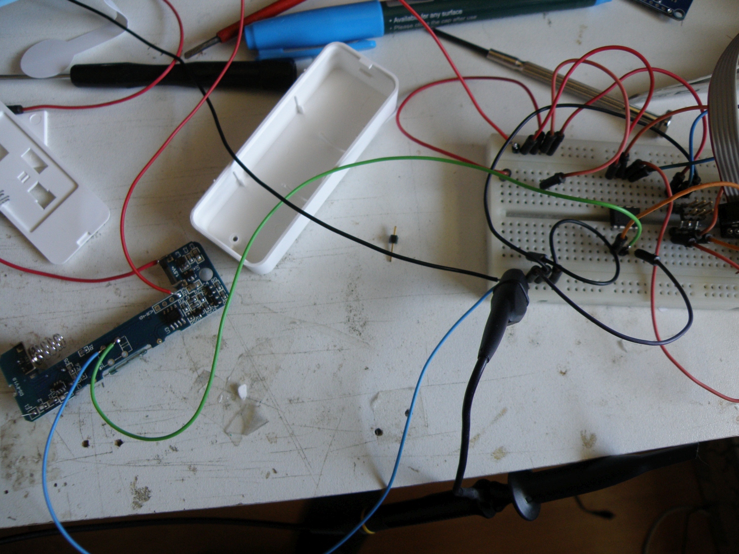
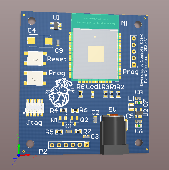
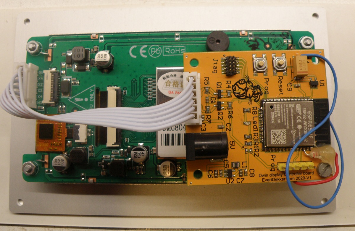
To connect the display to my domotica with the help of wifi and the mqtt broker I designed a piggy back to ( a short off) can be mounted on the back of the display.
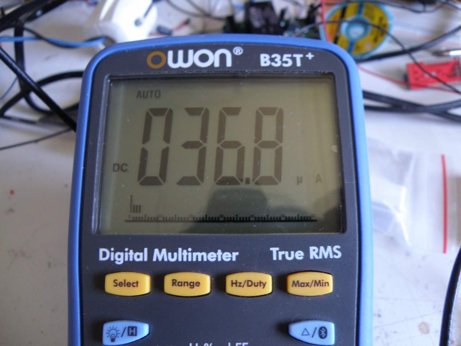
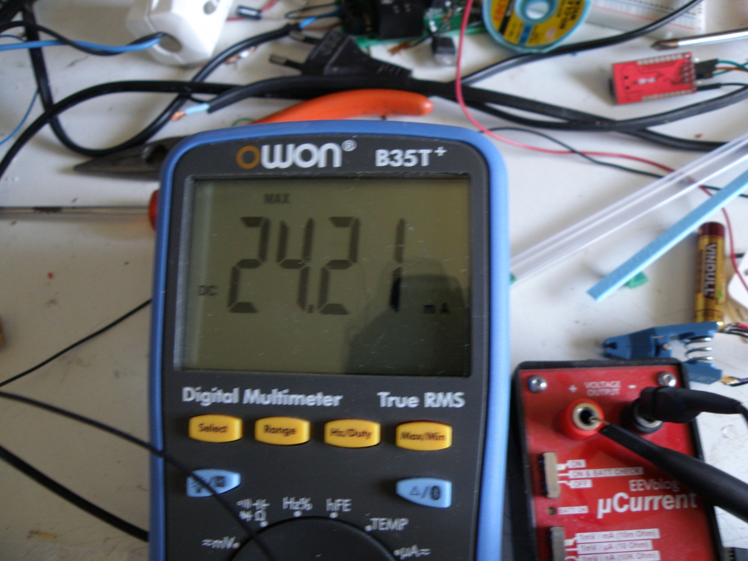
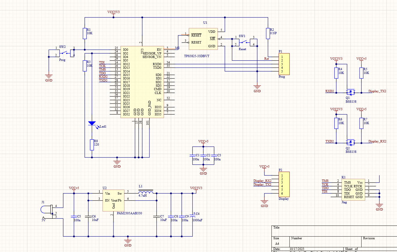
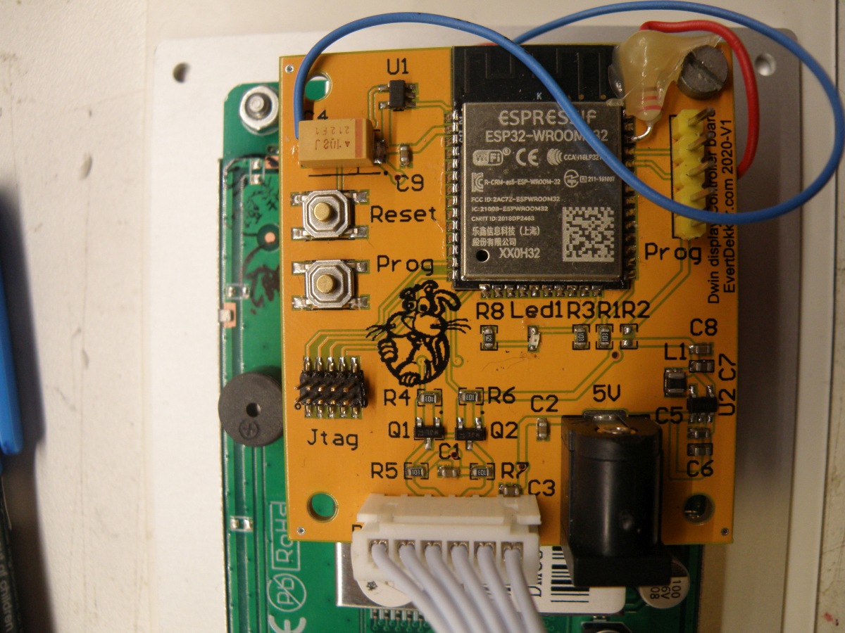
The hart of this module is an ESP32. Not a very special or difficult design. Used an ESP32-vroom with the TPS3825-33DBVT voltage supervisor for stable booting.
The Dwin display works on 5V and this 5V is available on the connector. So the display will supply the 3.3V power to the ESP32 with the help of an PAM2305AAB330 step down regulator. Not that special, used this setup in more of my design’s.
For level conversion for the 2 data lines the choice was made for a simple convertor with mosfet ‘s.
Pcb was designed in Altium 16 and the pcb made by my regular supplier elecrow.com.
Front panel bezel is made with the free software from Schaeffer Ag and the front panel was also made by Schaeffer Ag. This was the most expensive (€48) part of this project, however it’s the finishing touch that everybody will see.
And at last the firmware for the EPS32 has to be written. This is done in Visual code with the PlatformIO plugin.
All and all it has become a complicated project. You have to have knowledge of at least 5 (complex) software suite to get the job done and a lot of spare time, but it was fun and educational to do.
Have a look at the picture below for the result. The wifi status Led in the front panel is last minute added so there are the wires for soldered to the ESP32.
Can’t post all files here. If you need something let me know what you are looking for.
Here are the Altium designer file if you want to make your own pcb or use parts of it.