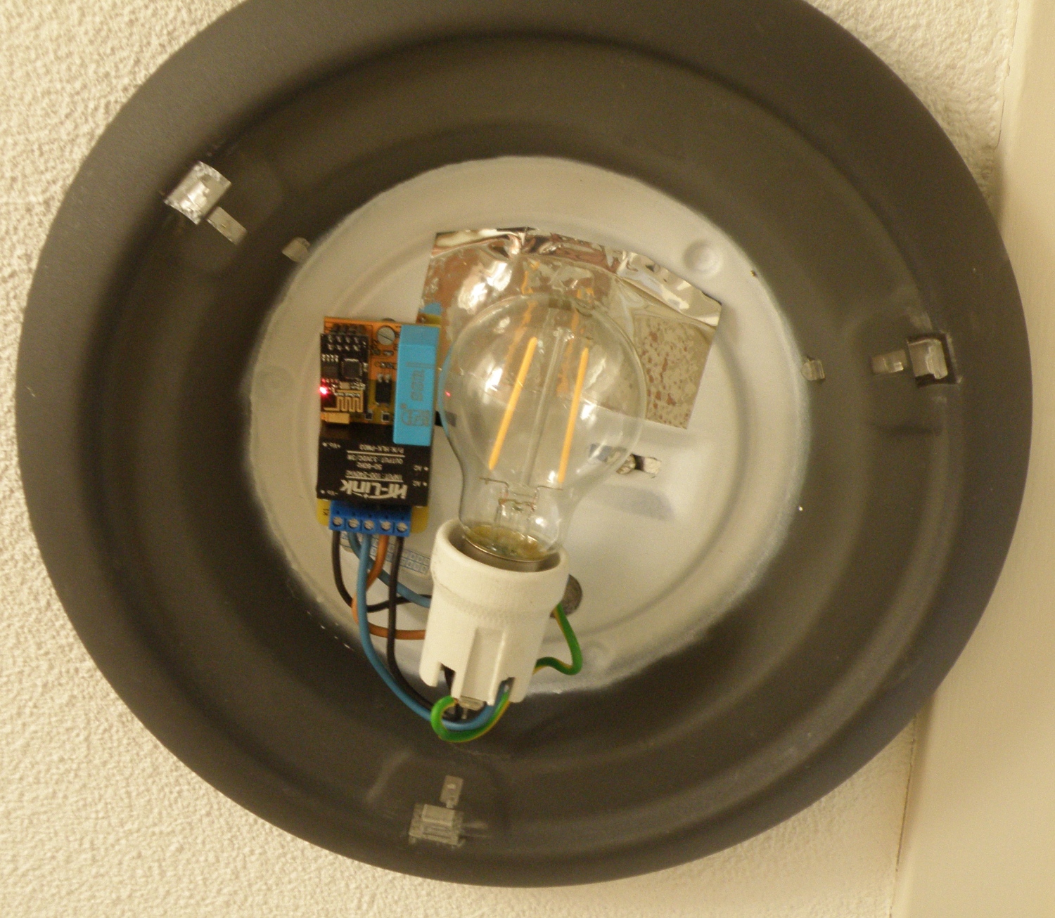
Iot light switch with mains input
IOT light switch with input for switch with mains.
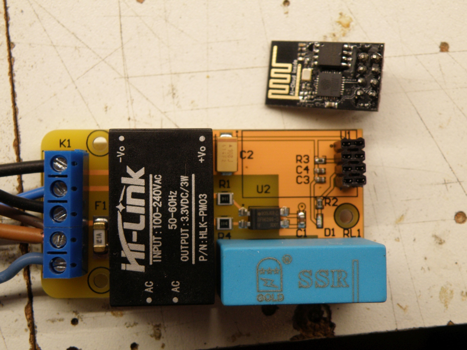
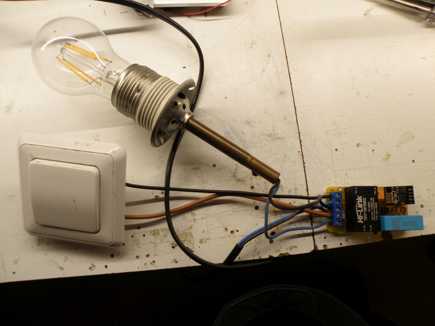
The idea is the same as the famous Sonoff wifi switch but this one has also an input for a 230V~ switch so you can still use your existing light switches.
Most of the light in my house is replaced with Sonoff touch switch , however this is not possible everywhere. For example on the stair case we have what’s called a switching circuit (wisselschakelaar for the dutch readers) and due to the wiring it was not possible to replace them both with a Sonoff touch switch.
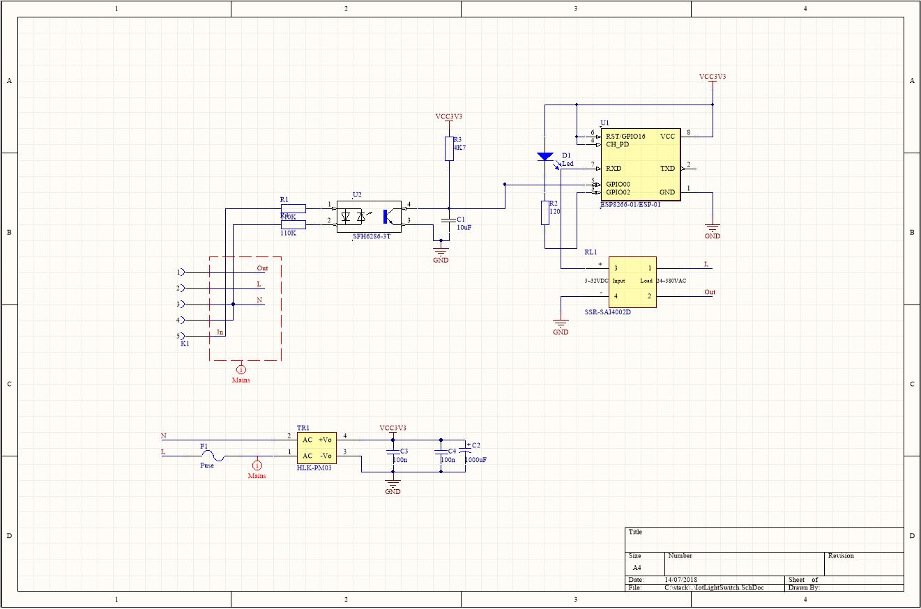
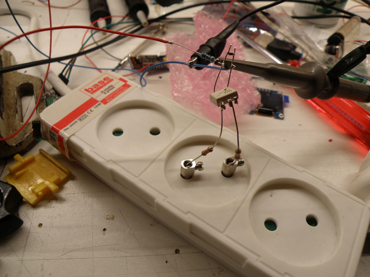
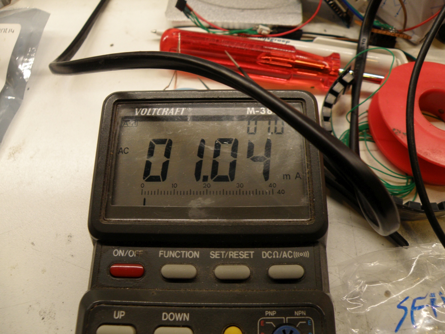
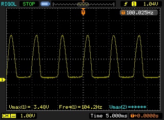
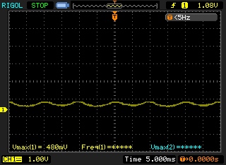
To detect the present of the mains on the input I started with a simple schematic based around the H11AA1 which you can find a lot on the net as mains or zero cross detector for Arduino. This worked flawless, see the photo of my experiment. With the CTR (current transfer ratio) of 20% it was necessary to have a current of at least 3.3mA through the led of the opto-coupler. With the used current limiter resistors of 2x33K this will dissipate 0.71W.
Not that much energy to “waste”, however depending on the state of the switching circuit and the Mqtt state this “wasting” can occur 24 hours a day, this can be done better.
Searching for an opto-coupler with a higher CTR should do the trick. The SFH6286-3 has a CTR of 100~320%, a led current of 1mA would be enough with this CTR ratio. 2x110K Resistor will limit the current to 1mA and will dissipate 0.22W.
That’s 0.5W less then before, that will save 4.36kWh per year maximum.
Note: All calculation done in this post where done for 230V~ 50Hz.
The rest of the circuit is not that special. The Esp-01 is programmed with an external programmer and then equiped with a OTA bootloader so programming is only needed to be done once (theoretically). To have enough room for the OTA bootloader and the sketch I have updated the memory from the esp-01 from 1MB to 4MB. That’s easy done with a hot air gun to replace the memory chip. 4Mb spi flash chips can be bought very cheap on ebay.
The solid state relay will consume 6mA at 3.3V, this is broad within the max pin GPIO current of the ESP8266 so no transistor driver is needed.
Because the Esp-01 doesn’t have that much IO pins available the RX and TX can also made be available as IO, to disconnect them from the uart use:
pinMode(1, FUNCTION_3); //GPIO 1 (TX) swap the pin to a GPIO.
pinMode(3, FUNCTION_3); //GPIO 3 (RX) swap the pin to a GPIO.
You can still use the TX/RX pin to program the ESP-01, but using them in your sketch is not possible anymore. To still have the possibility to debug I use a remote debug library to debug over telnet.
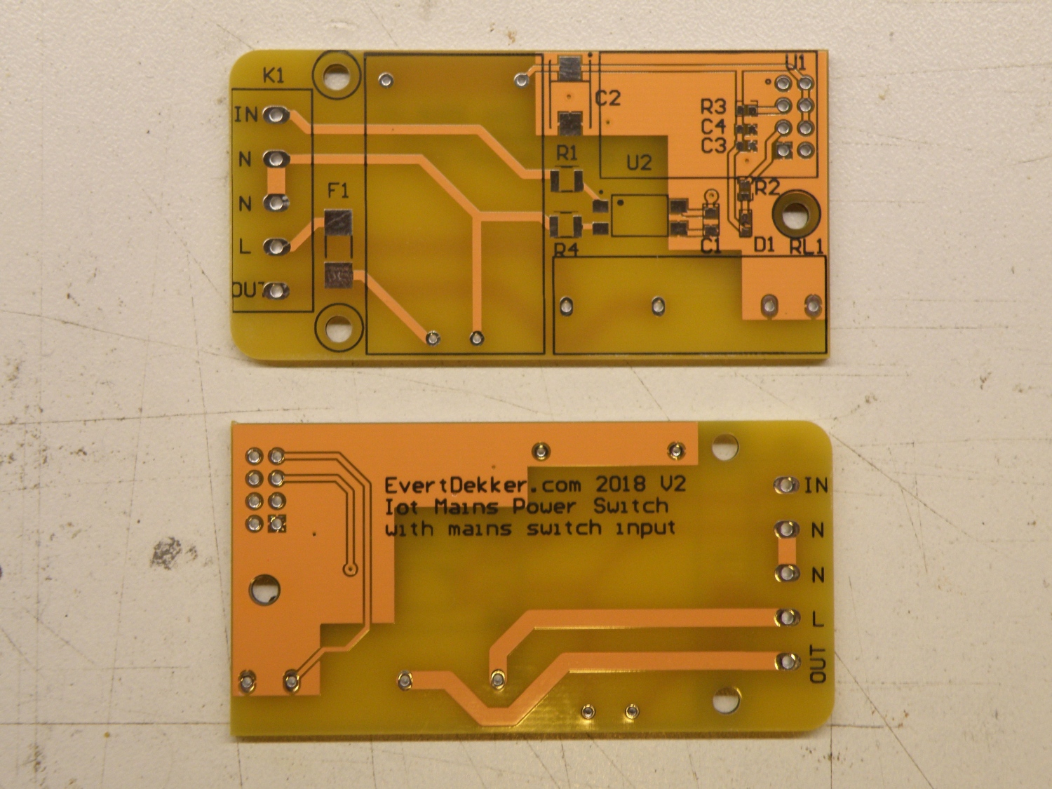
If you want to make your own, or use parts of the design here are the Altium Designer 16 files:
