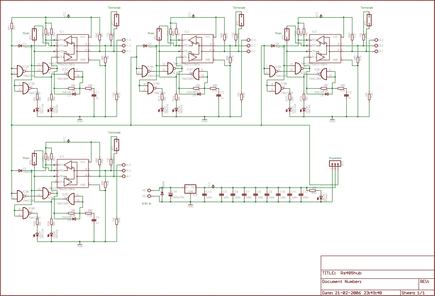
Very simple design half-duplex Rs-485 hub.
You can split up your network in different segments for stability or expand your network with more device’s.
Every i/o can individual terminated.
Hub can be stacked with the expansion connector.
Primary designed for the Joshua Bus
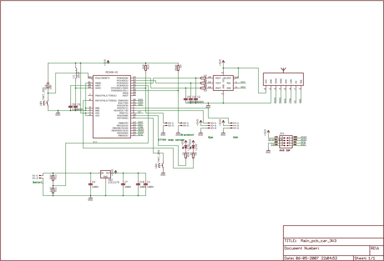
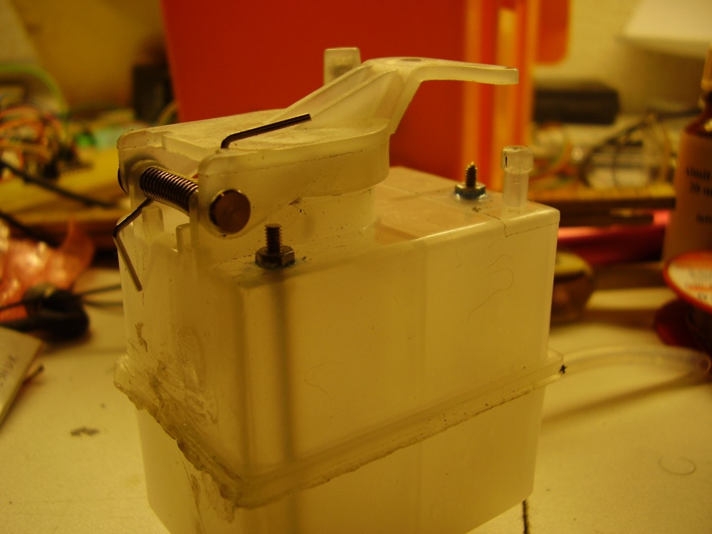
This device will transmit some parameters wireless from my Rc-nitro car to a hand held PDA.These parameters are; Motor RPM, Speed KmH, Fuel level, Battery voltage, Engine temperature and 3-axis G-force.
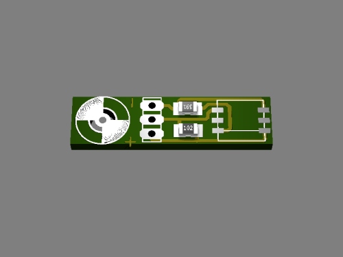
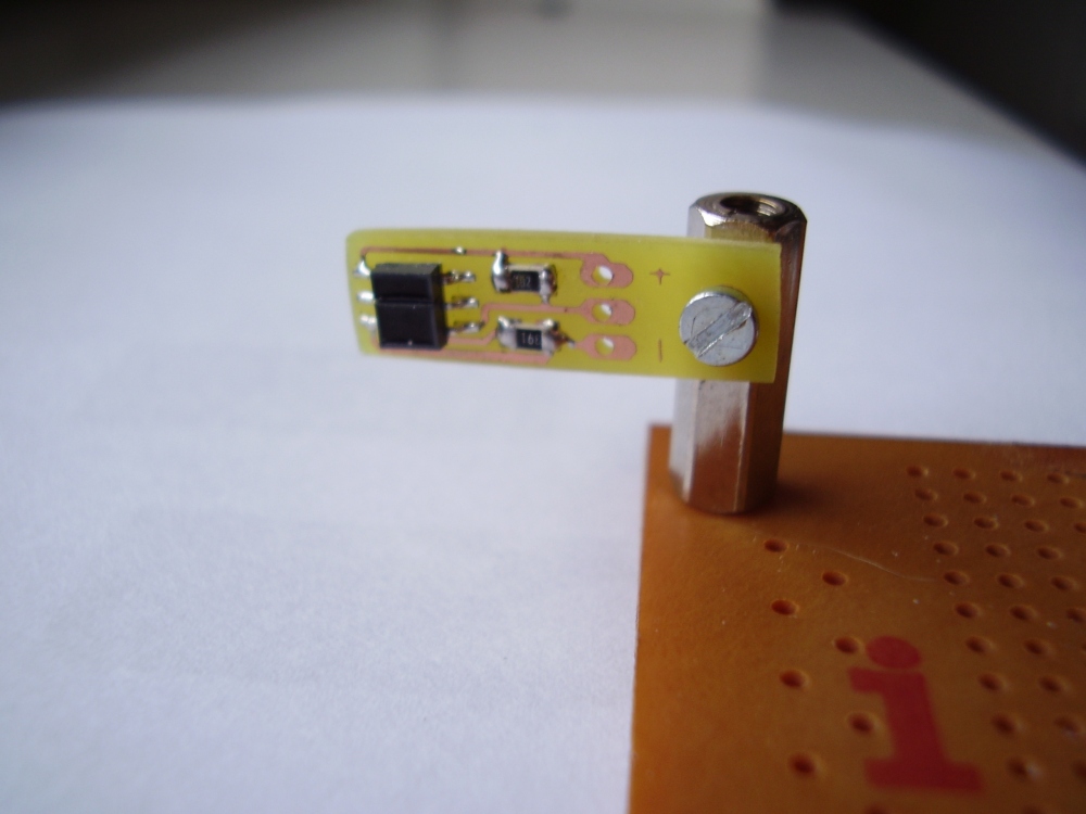
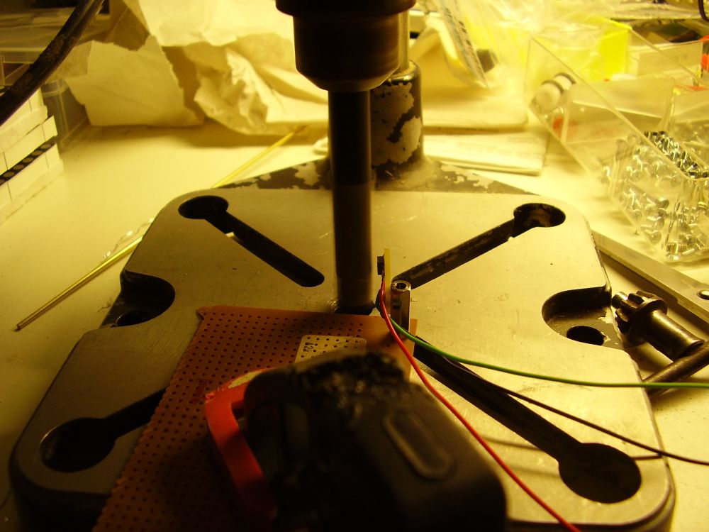
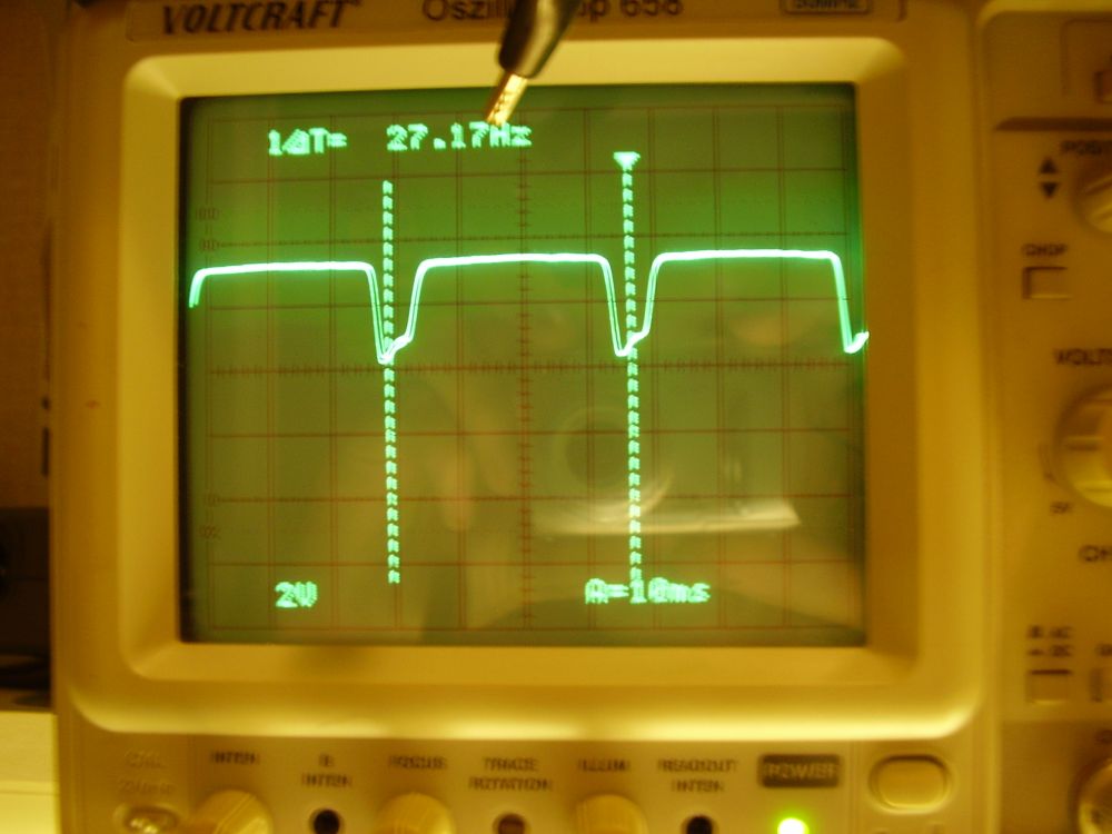
First we need to design some sensors. For the RPM and KMH we are going to use a reflection sensor . Due the high RPM it was not possible to mount a magnet to the motor or drive shaft. The reflection sensor will give a pulse when the reflection goes from light to dark or dark to light. The sensor is only available in smd package, so we need first to design a carriage board. Testing the board was done in a drill and the sensor was working very well up to 1,5mm from the drill shaft.
Next sensor needed is the fuel level sensor, just 2 M2 bolds to measure the resistance of the fuel. How higher the level is more of the bold makes contact with the fuel, how lower the resistance. I’m not sure of this sensor will work in the real world, reading is very unstable due the sloshing of the fuel. Did also some experiments with capacitive measuring, but ill try this first.
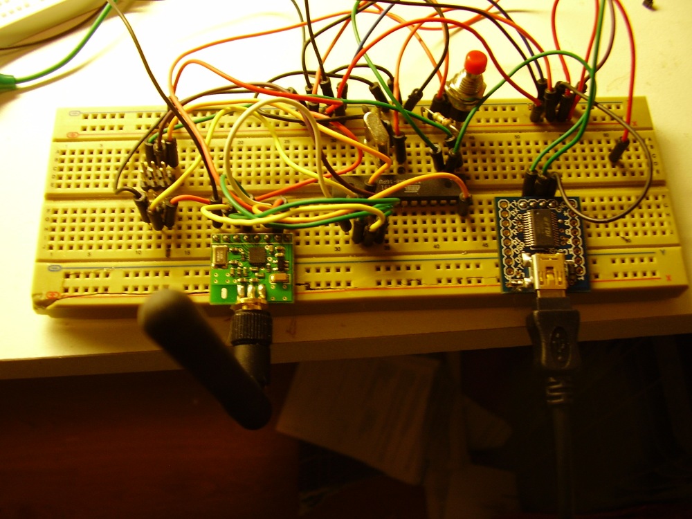
Now we go testing the wireless connection. First I want to use the cheap 433Mhz transmitters, this was working good with some manchester coding and crc. The problem that I noticed was that the 433Mhz was full of other “things”, for instants i know now that my neighbors has a logitech wireless mouse. Then I tried Bluetooth, that was also working very well, but i want my application running on a PDA and there was no bluetooth classe 1 CF card on the market. Bluetooth was also not cheap and compact. Then I run in the Nordic nRF24L01 2.4Ghz transceiver. It was compact, cheap and smart. Please read my application note fore more details. The Nordic will do retransmit, crc, ack , etc… by itself and fast. I hope that 100 meter range will be enough.
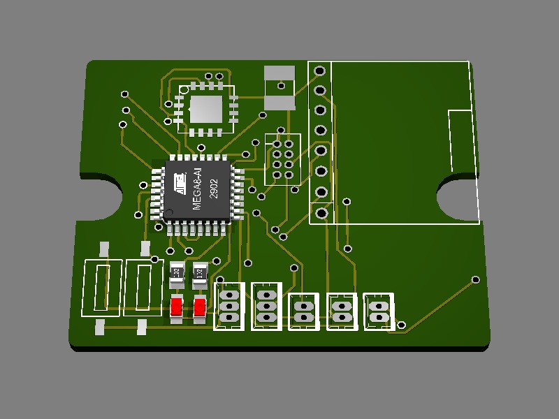
First schematic was running on 5V, but the nRF24L01 and the MMA7260 (1.5g – 6g Three Axis Low-g Micromachined Accelerometer) sensor requires 3,3V, so decided to make everything running on 3,3V.
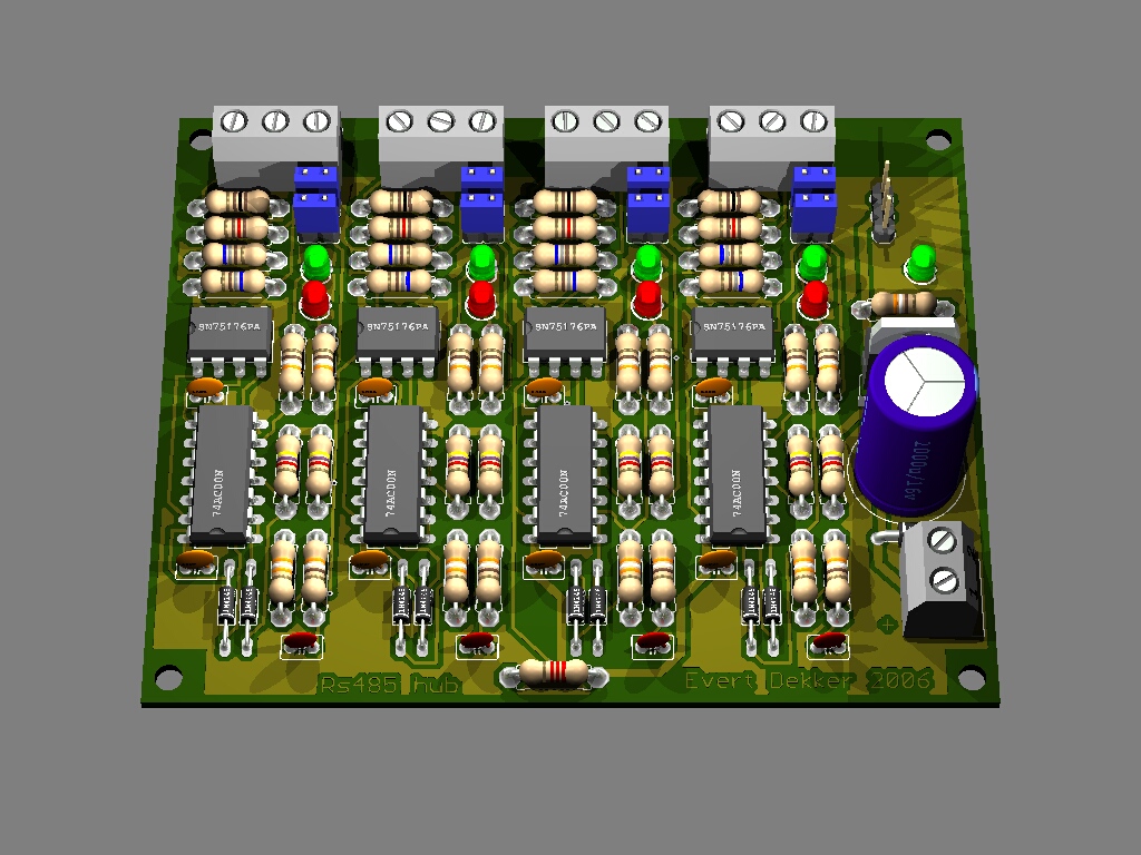
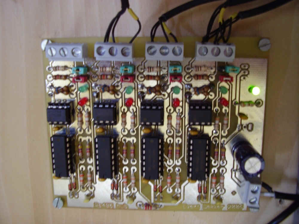
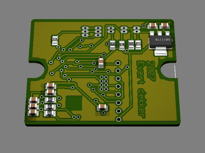
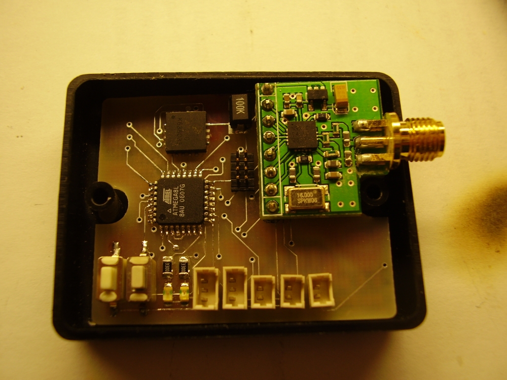
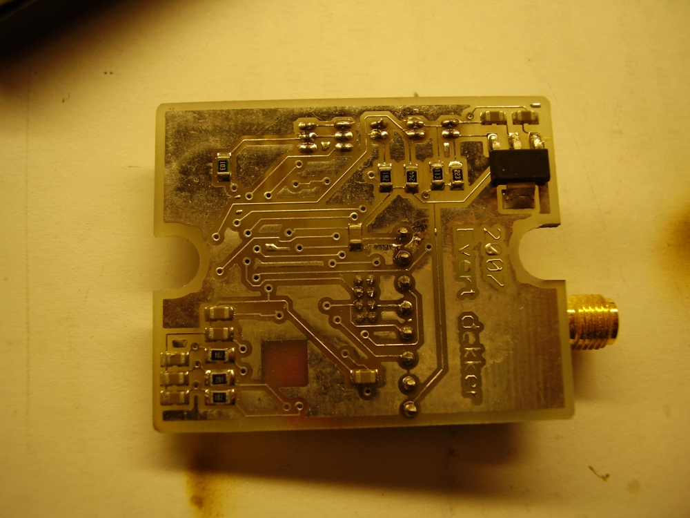
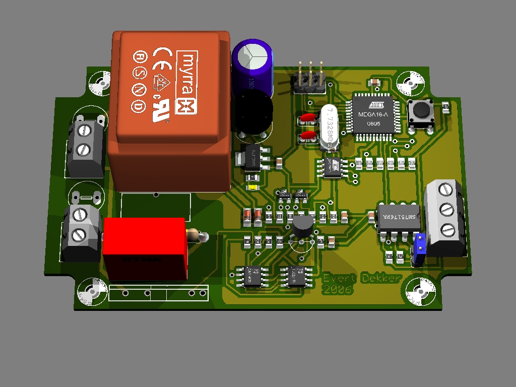
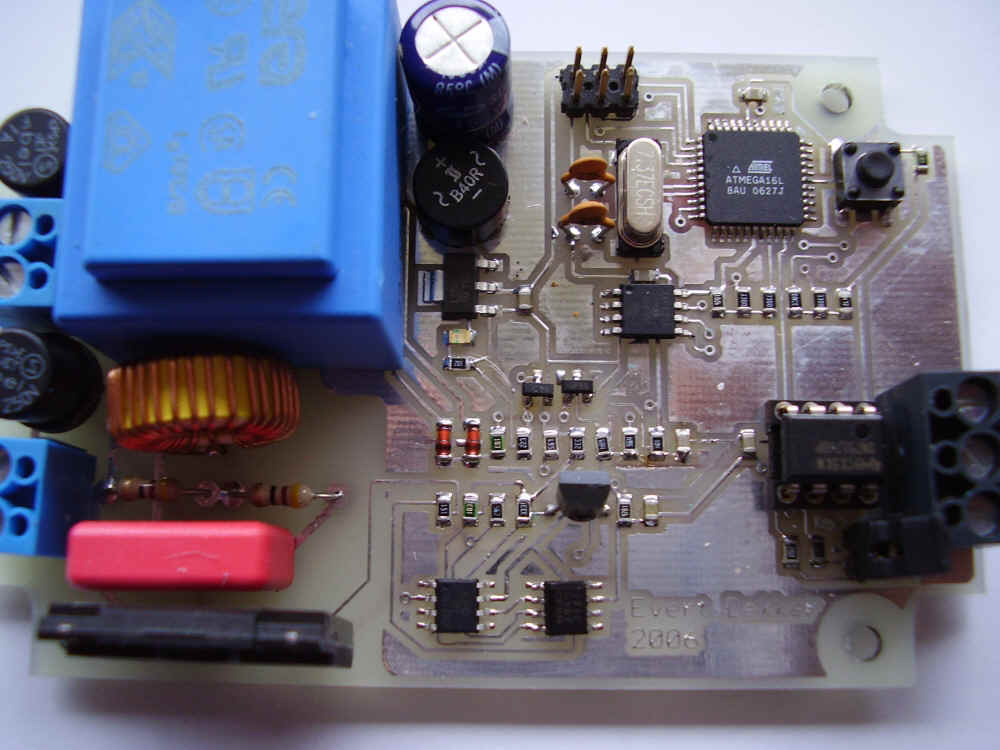
Schematic is finished and pcb is designed and made.
Soldering the MMA7260 was not that easy. Notice the 6x6mm Qfn16EP package in the upper left corner, very difficult to solder because there are no leads.With some solder paste, heating gun, patience and 3 retry s it’s done and working.
For some mood lighting in the living room I mounted a lot of rgb leds in the cabinet. Rgb leds will be driven with 3 pwm channels on a Atmel mega-128. Controlling will be taken care of by the Joshua Bus .
Testing the leds:
RGB Dimmer Test
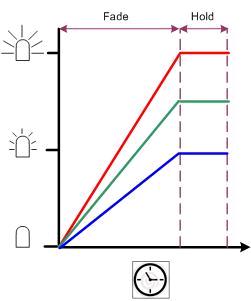
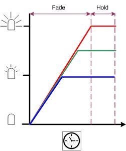
For a nice fading it’s necessary that the fading will work like figure 2. In figure 1 all colors are increased every step with the same value, the disadvantage of this is that blue is finished first, software is easy to make. In figure 2 all colors are finished the same time, the step size for all colors is different. I wrote a routine that will take care of this.
Nice fading example:
RGB dimmer fade
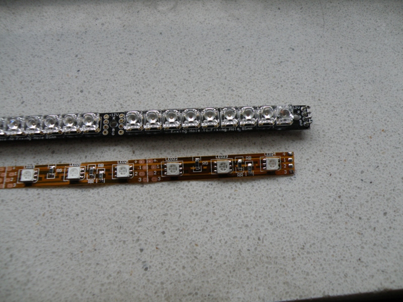
Update: Replaced the ledstrips. The old strips had 3 leds for the colors, separated Red, green and blue led. This was not mixing very well and because the strips are close to the wall you could see the individual colors on the wall.
Placed now new strips with RGB led’s in 1 package.
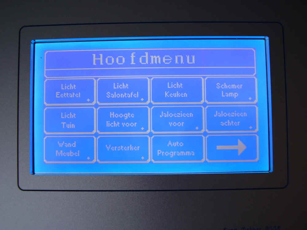
After building a 3″ touchscreen for the Joshua bus i decided to make a 5″ touchscreen for the livingroom.
The problem with electronics is that continues changes, touchscreen not available anymore. Find a new supplier with nice priced screens Ledsee.com . Screen has a compleet new pin assigment so we must design a new pcb and some minor software changes.
See the touchscreen in action, take a note of the moving buttons.
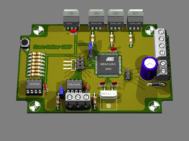
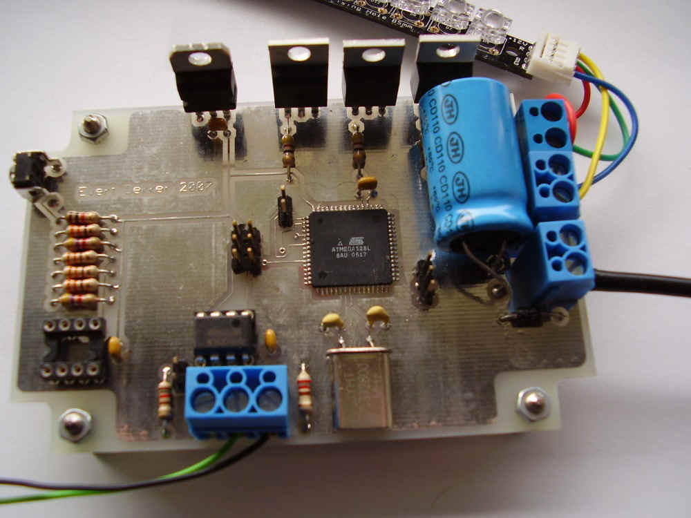
This is the (almost) the same dimmer as the dinnertable dimmer for the Joshua Bus . This version is compacter due the use of smd components.
3D Design
Finished pcb
We use cookies to ensure that we give you the best experience on our website. If you continue to use this site we will assume that you are happy with it.