Making of the CoLinkEx
How did I made my pcb version of the CoLinkEx…
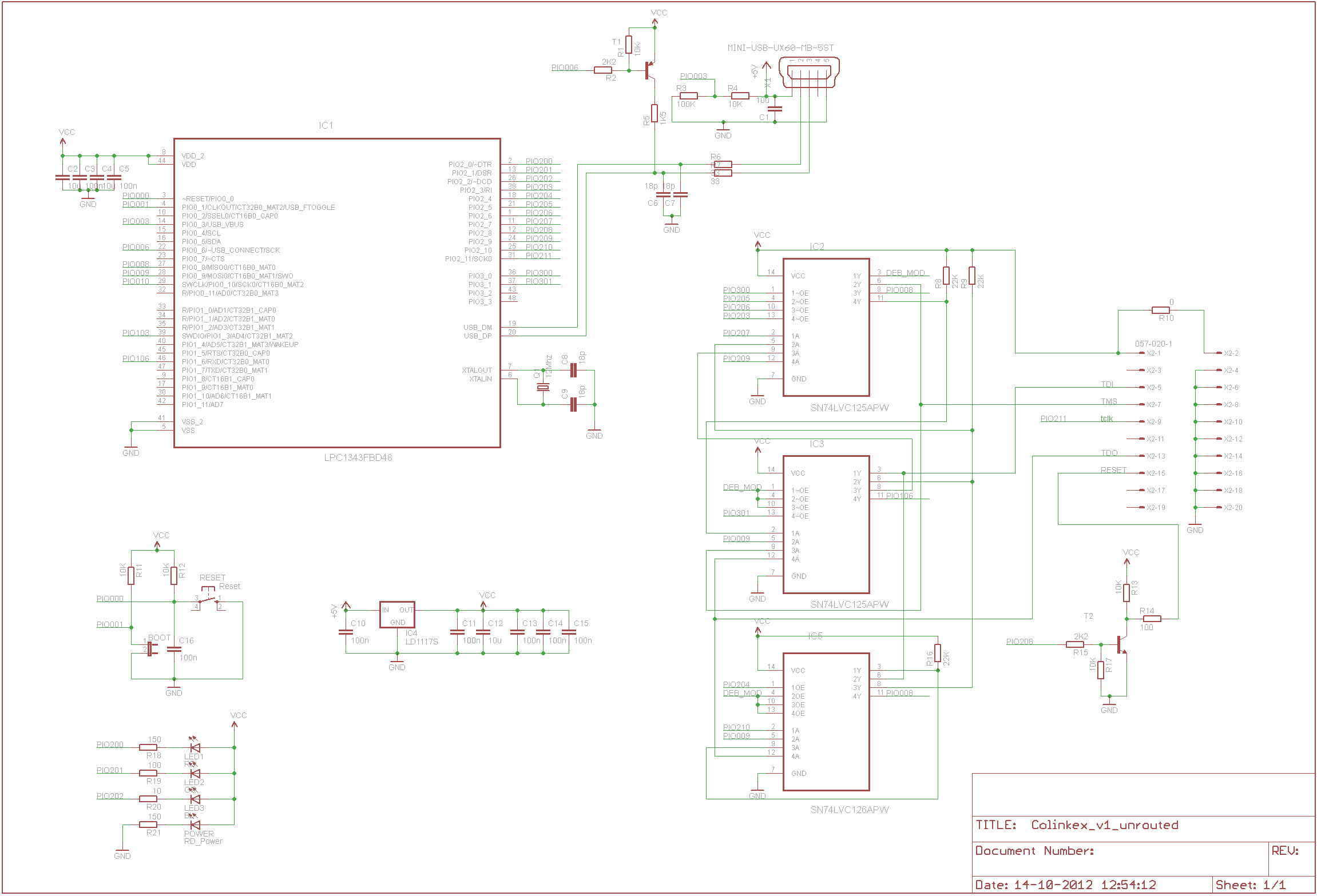
First of all I borrowed most of the schematic from Coocox. Made some minor changes for components that are not that easy available in Europe and ported the schematic to Eagle.
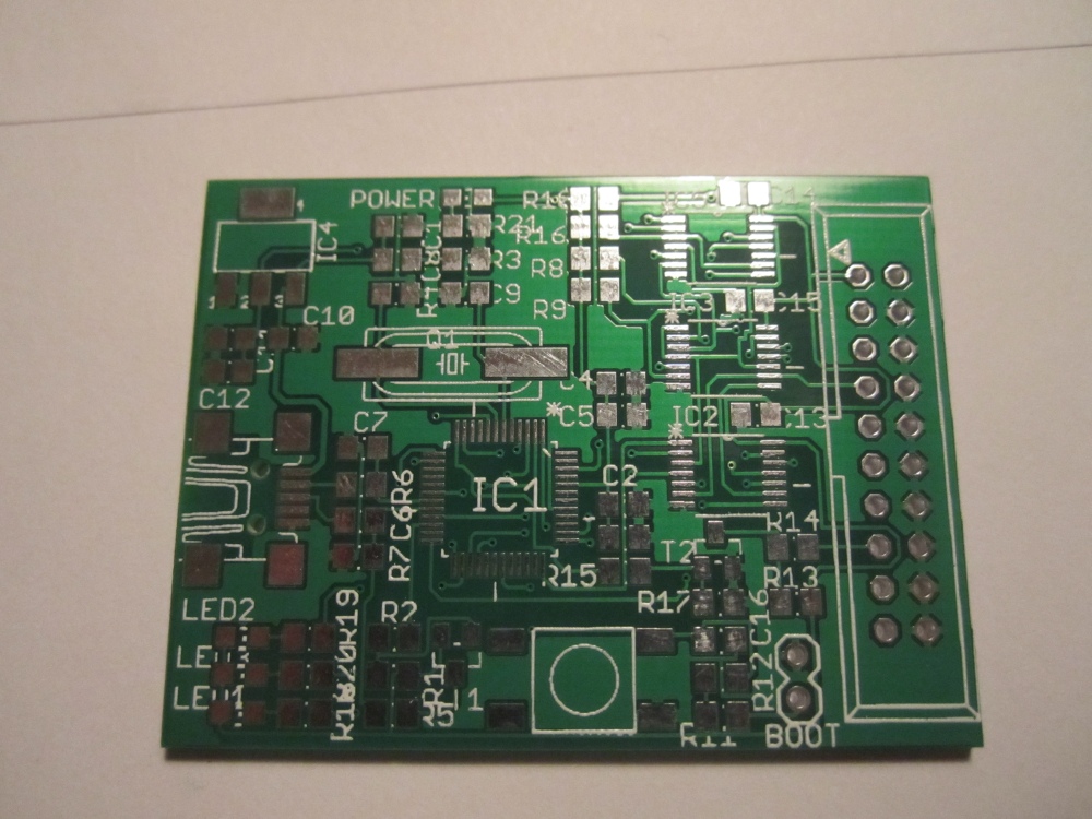
Uploaded the gerbers to my pcb manufacturer Elecrow.com in China, there are cheap but delivery can take up to 3 weeks, doesn’t matter if you’re not in a rush, the price and quality is perfect.
Because the plan was to make 5 pieces of the CoLinkEx and there are some fine pitch chips on it fabricating them would be the easiest with the stencil and reflow method.
For this small amount of pcb’s a stencil made from polyester will do the job fine. From Smtstencil.co.uk you can order an a4 stencil for around €15. You can put as much designs on it as you like. I prefer the 100μm thick sheets, there applying enough solder paste to the pcb.
First we have to make a framework to hold the pcb steady and align the stencil correct.
The framework is easy to make from some pcb leftovers that have the same thickness as the Colinkex pcb, standard pcb is 1.6mm thick. Glue the pieces on a bigger pcb leftover or other material. You can use almost everything for this.
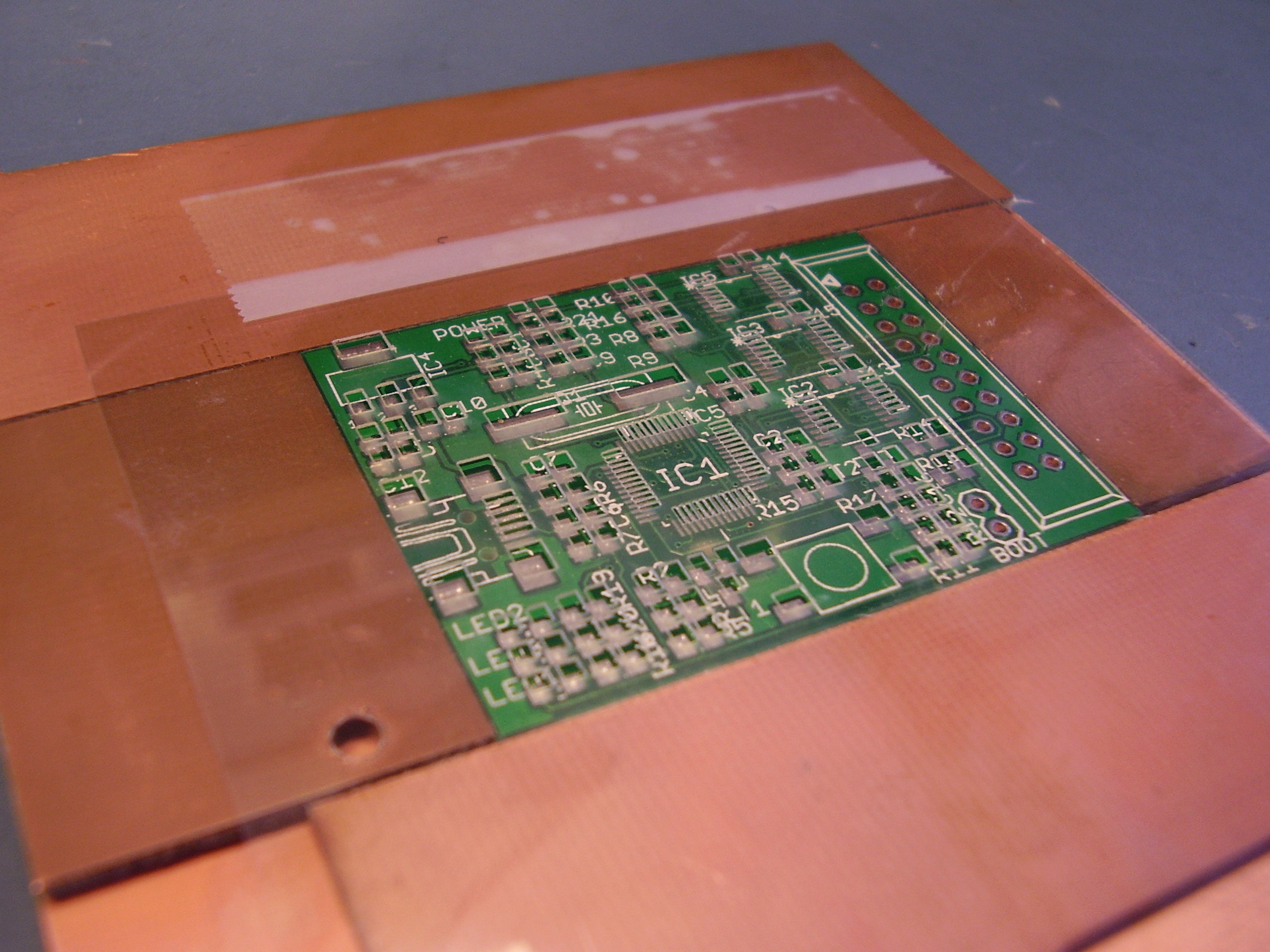
Put the pcb in the framework and align the stencil exact as possible with the pcb. Then tape the stencil on 1 side to framework.

When the pcb is removed you can see clearly the cutouts in the stencil.

Now lets apply the solder paste. Put a line of solder paste as wide as the pcb is on the same side as you have applied the tape.
Smear the solder paste with an spatial over the pcb. First run hold the spatial in 45 degree angel to push the solder paste in the cut outs. Smear always from the tape away to prevent moving of the stencil.
Second run hold the spatial in almost an 90 degree angel to “scrape” off extensive solder past.

Lifting the stencil and voila , nice layer of solder paste. After removing the pcb carefully I repeated the previous step to apply solder paste to the other 4 boards.
Looks like it’s completely failed, especially the fine pitch (0.5mm) LPC1343FBD48 cpu. But when reflowing all the solder paste will end up on the leads due the capillary force.
Placing all the components on the pcb, just put them exact as possible in the solder paste. A little bit out of alignment is not the worse, during reflowing it will correct itself.
In this video from an other project you can see how the components will align them self when the solder melts in the oven.
Still missing some components, I thought that everything was on stock. Doesn’t matter can place these components later an solder them by hand with an iron.
Now time to place the pcb in the oven to reflow it.

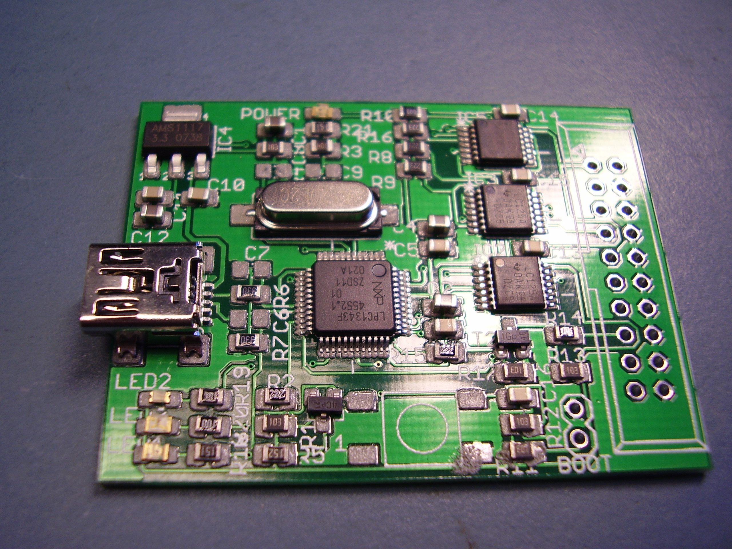
Finished reflowing. Added the jtag header, still waiting for some components
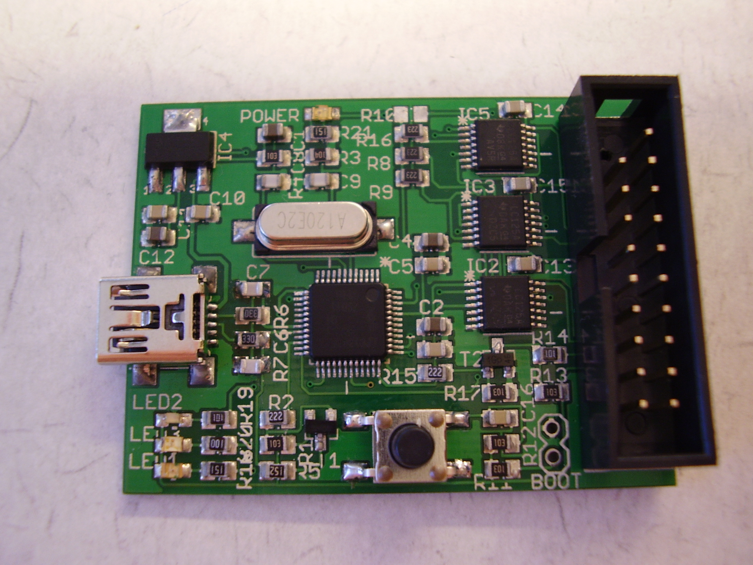
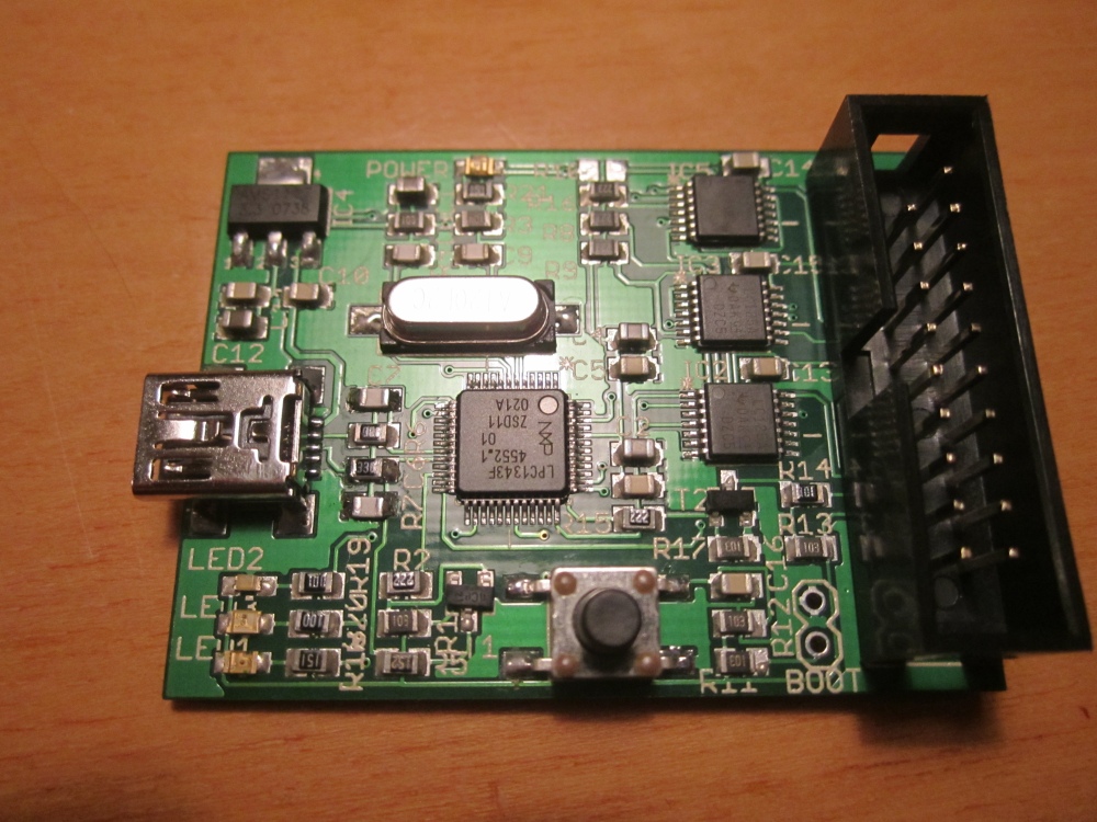
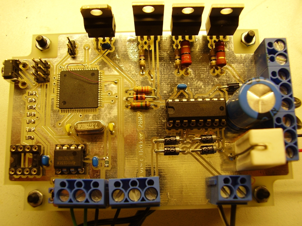
All parts are in, finished now soldering the board.
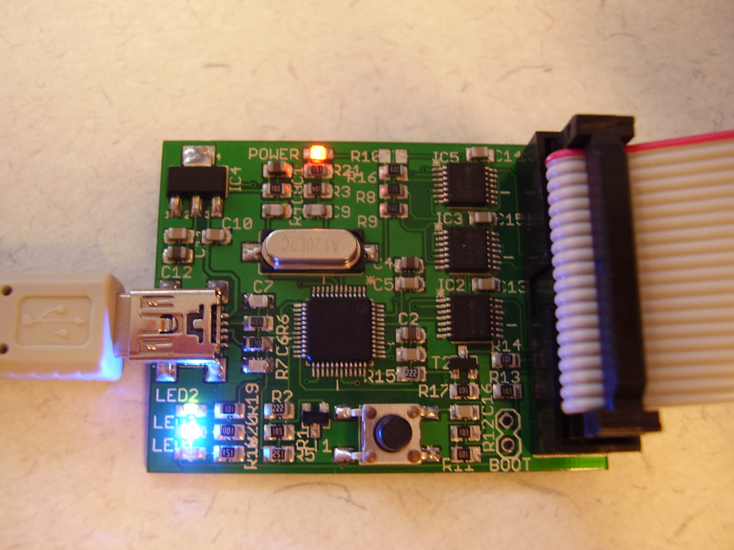
It’s alive, working well.