Just like in all other Sonoff products one of the leds is hardwired to the relay and will lit up when the relay is switched on.
In my post over the Sonoff Wifi powerline switch mod I described how to put the led on a seperate IO pin of the Esp8266 so you can get full control over the led.
This post will do the same for the Sonoff touch led that’s behind the touch sensor.
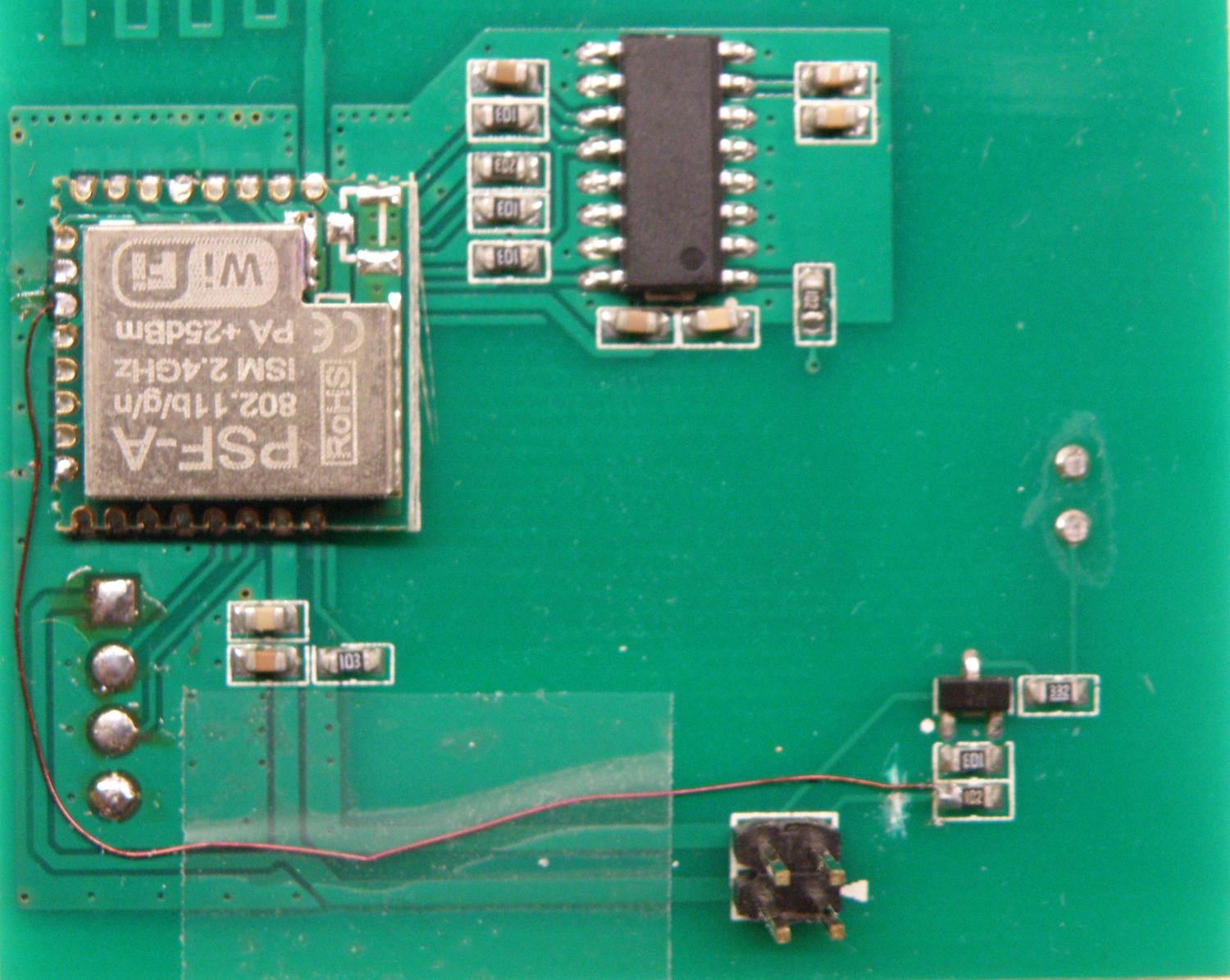
The Sonoff touch has an Psf-a85 module on board from Itead, this module has the esp8285 inside. With the pinout and schematic available of the psf-a85 it’s easy to find the required pins.
You need to scratch the pcb track that’s going to the 1K resistor (see picture below). After that you need solder a thin wire between the 1K resistor and one of the free IO pins on the psf-a module, in the picture I choose pin 3 IO4.
Now you have full control over both (wifi and touch) led.
My idea was to let the touch led glow so you can find the touch button easy in the dark.
If you don’t know how to flash the esp8285 have a look at this.
Personally I add to all my ESPxx programs the OTA (over the air) flash capability’s so you can remove the usb to serial convertor and close up the housing for safety purpose and flash new firmware ota.
Arduino ide settings:
Generic Esp8285 Module
CPU Frequency: 80MHz
Flash Size: 1M (64K SPIFFS)
Upload Speed: 115200
Now the shorter days and the longer nights are arrived in The Netherlands it’s dark outside when leaving or coming from work.
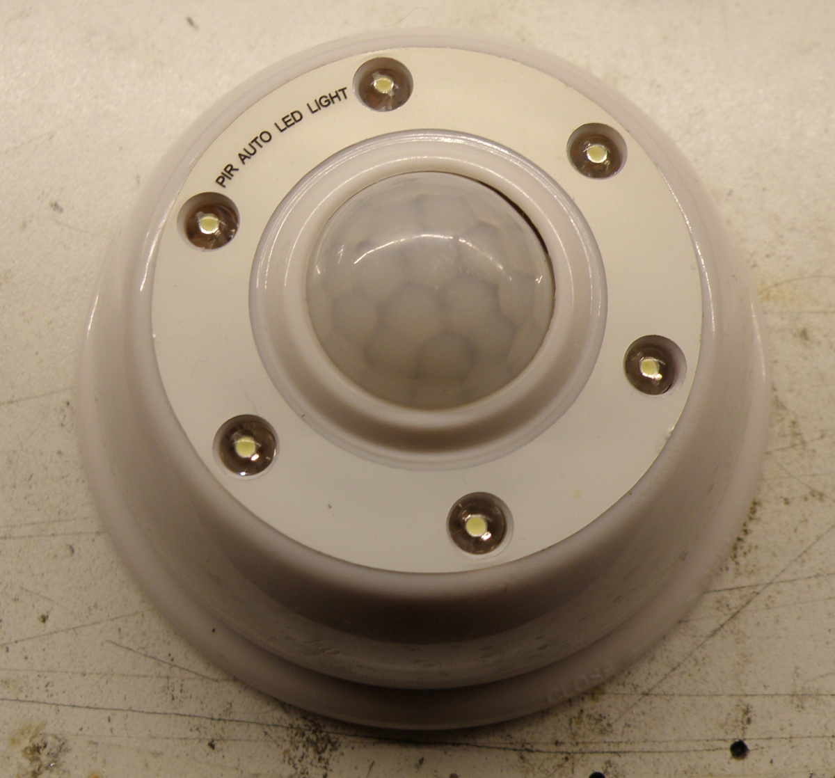
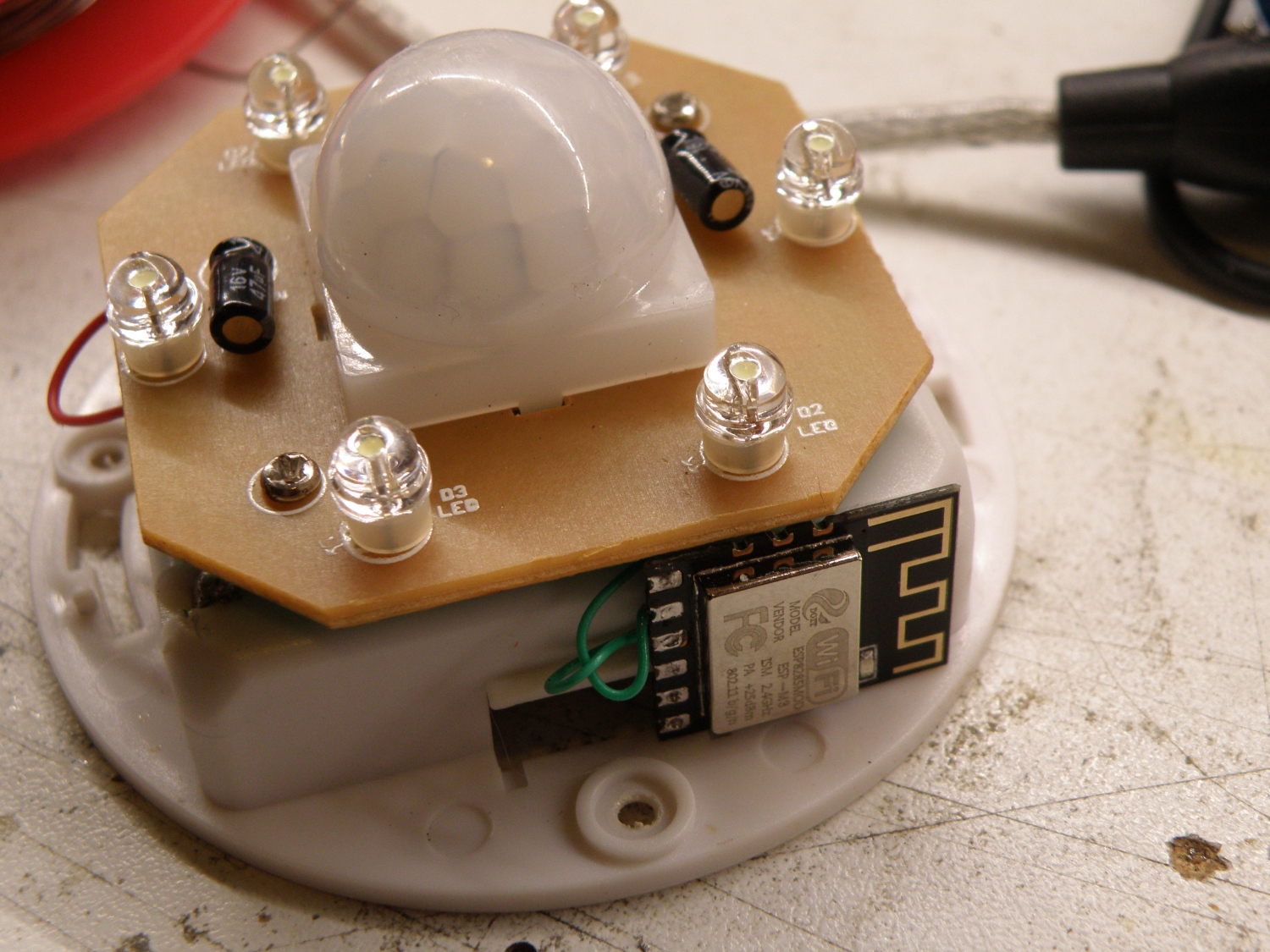
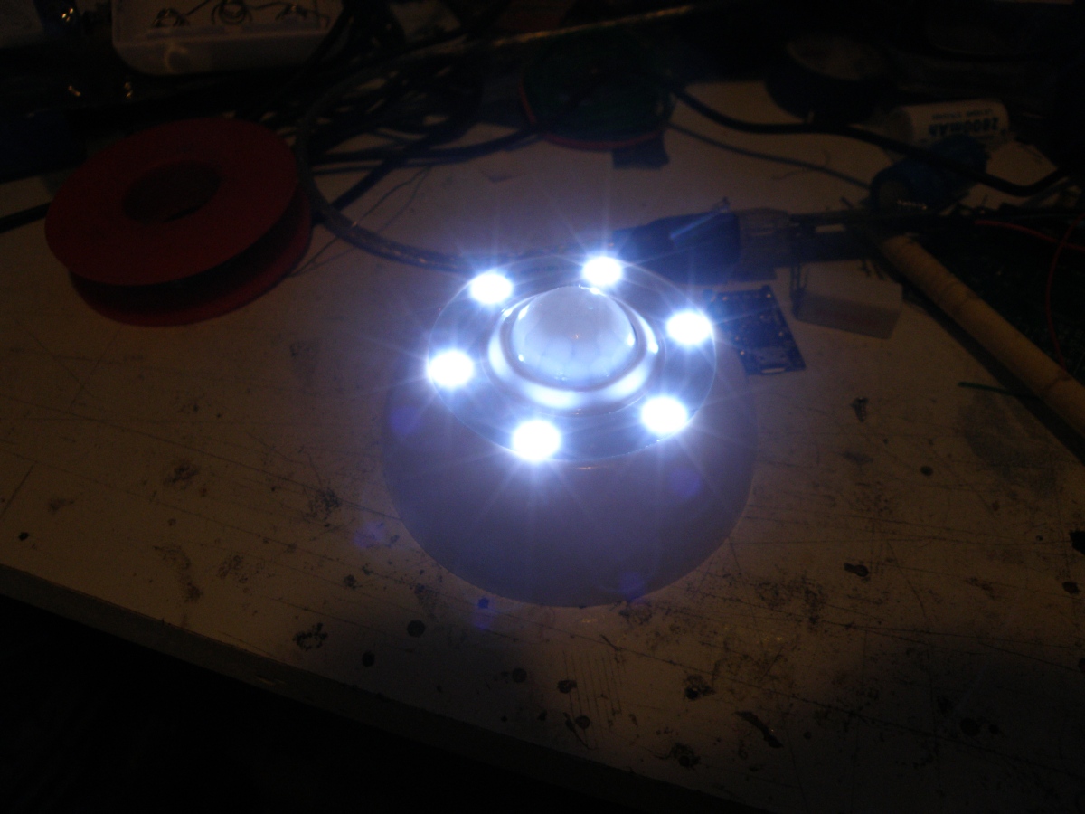
From Ali express I bought some battery power led light with build in pir (passive infrared) and light sensor. Very handy, you stick them somewhere above the door with some dubbelsided tape and they will light up if some one, good or bad will approach the door.
It will also be handy if I get a notification on my smartphone if some approached the door, so the idea was born.
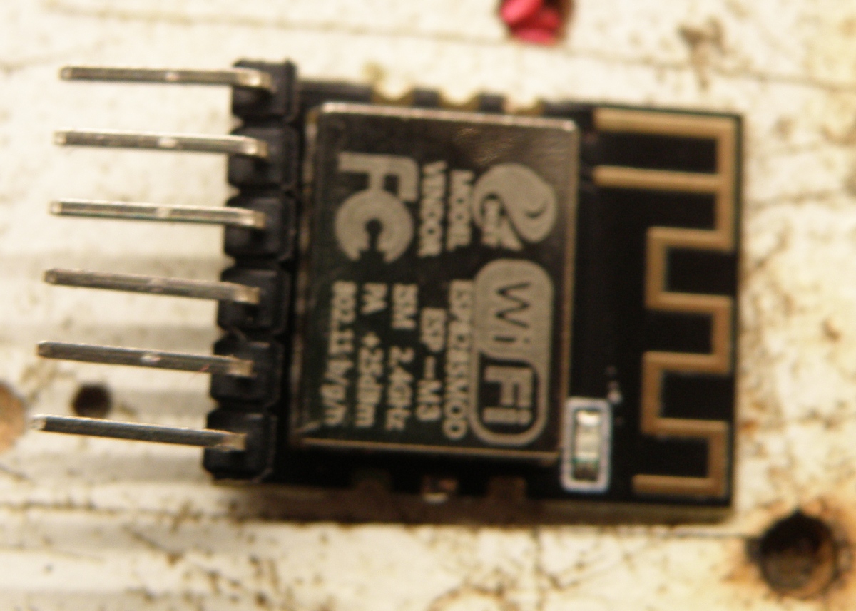
Because I already had some domotica system with Iot (Internet of things) running it would be handy to integrate it with this. The small esp8285 Esp-M3 module was the one that will do the job, mostly because it’s small of size. It will send a message to my mosquitto broker and with node-red it will handle the message.
The pir led light is battery powered so very low or no power consumption was required.
The idea is that when the leds are going on, the esp8285 will connect to the wifi, send a message to the broker, and then go in deep sleep. When the leds are going off again the esp8285 will be switched of completely and will therefore draw no current anymore.
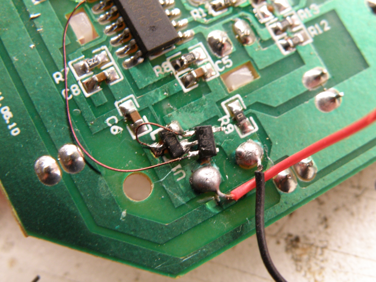
After studying the controller (BISS0001) in the pir led light it was not that difficult to accomplish. Finding the correct output pin with the help of the datasheet was easy. This pin (2) will become high when the leds are turned on by the pir detector. With this is should be possible to switch on the esp8285.
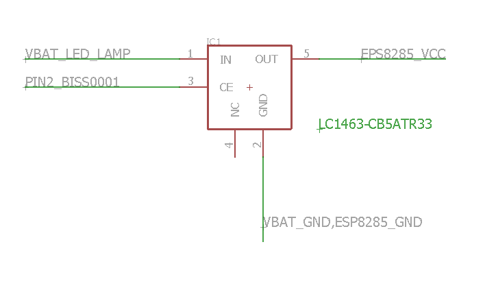
The pir led light works on 4×1.5V battery and the esp8282 on 3.3V, so we need also a voltage regulator to get the correct voltage. The idea was to combine the switch on and regulator part, this made me choose for a regulator with an enabled pin. Also was it important that the regulator does drawn as low current as possible when disabled. Google and ali-express gave me the LC1463, a fixed voltage regulator that can deliver up to 300mA and draws only 0.1µA when disabled, perfect for the job.
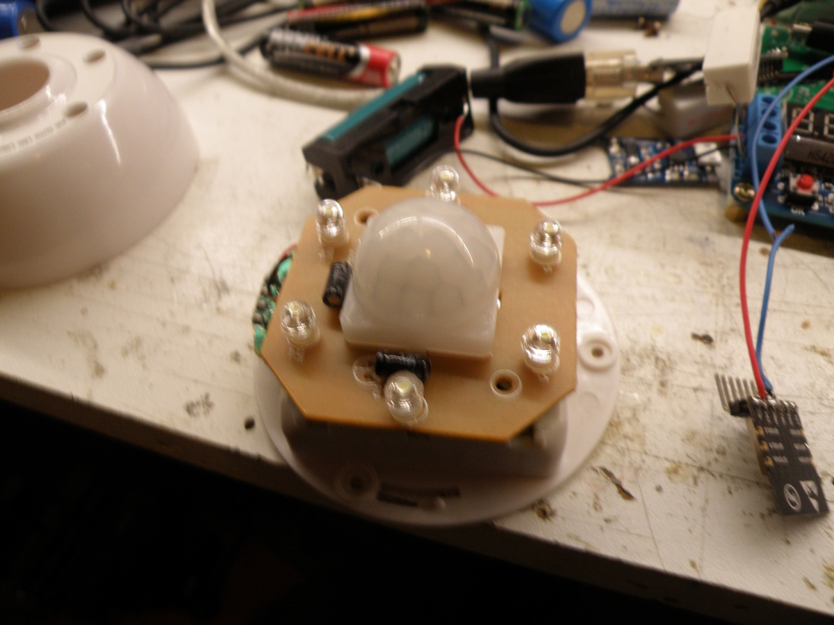
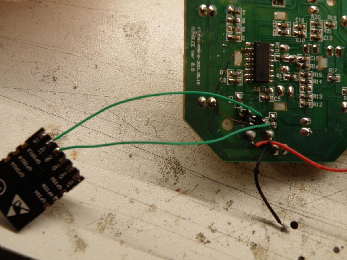
This time no designed pcb, but floating wiring the parts together in the pir led light with roadrunner wire.
Have a look at the schematic and picture to see how to connect. Not all the pir led lights from China are the same, but if they have the BISS0001 controller inside and you can locate the plus and minus coming from the battery it’s easy to connect.
Before soldering the esp8285 module in the pir led light you have to program it first. For this you need to connect the Vcc, Gnd, Txd and Rxd to your Usb to serial convertor. After plugin the convertor in the USB port you have to bring the esp8285 in download mode by resetting it and holding the GPIO0 to gnd. So for this you need to solder also an wire to reset and GPIO0. If the blue led on the esp8285 module short flashes it’s in download mode.
After downloading and testing the sketch you can remove the header, the reset and GPIO0 wire again. Be sure that your program works.
It’s also possible to bring the esp8282 in OTA (Over The Air programming) after programming, this can be done be placing the value 15 in the “/vm/tuin/pirsensorachter/status” topic. For more details see the sketch on github.
Current measured: 56µA when standby, 130mA when leds and wifi on (takes 4 seconds to login wifi and send message to the broker), leds on only 60mA.
We use cookies to ensure that we give you the best experience on our website. If you continue to use this site we will assume that you are happy with it.