PZEM-016 Energy Monitor
 I bought some (2pieces to start) PZEM-016 energy measure modules from Ali express. You can get them for around $8, not that expensive at all if you take in consideration what this device all can do.
The idea was to measure in my fuse box all the groups (6) separately and push the data to my Mqtt broker over Wifi with the help of an Esp32 and Arduino.
As always the idea was born quick, but to get it all working together was a bit harder, partial because of faulty (not sure about that) manual, other bugs and even something stupid as a bad power supply. But, never give up and it’s now working fine.
The PZEM-014/016 can measure Ac voltage V, current A, active power W, frequency Hz, power factor pf and used energy Wh. You can read all these values from the PZEM with the help of a Rs-485 Half duplex bus. The protocol they used is the well known modbus protocol.
Note: The Rs485 side is safe, but the rest of the PZEM-014/016 has deadly mains voltage. Please be careful.
The schematic is not that special, if you worked before with Rs485 you will recognize the parts.
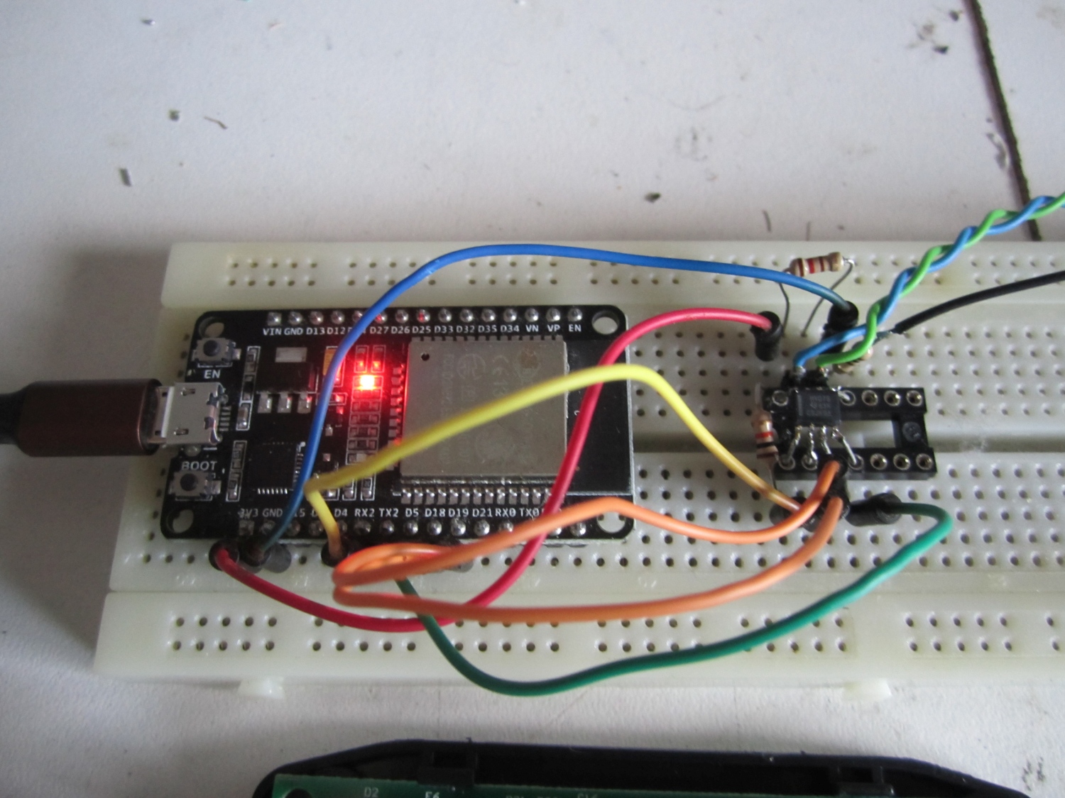
As Rs485 line driver I used the SN65HVD75 from Texas Instruments, why? Because that’s the one I had on stock. You can use every Rs485 driver for it, however keep in mind that is should work with Vcc of 3.3V provided in the case by the ESP32 Devkit V1.
The data in and out of the Rs4854 driver are connect to the 3e (uart2) hardware port of the Esp32. The data direction (RE_Not/DE) selectors are connected to 2 gpio of the Esp32. You can connected those pins also together to one gpio.
And now something about the RS485 bus.
 It’s important that you do this correct to get it all reliable. A good Rs485 has at the begin and the end of the line a termination resistor of 120Ω. So it doesn’t matter if you have 2 or 20 devices on the bus, you always need 2 termination resistors. Why, to get load on the line and prevent reflection of the signal. Google for it.
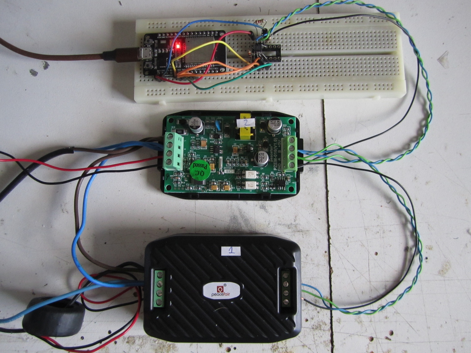
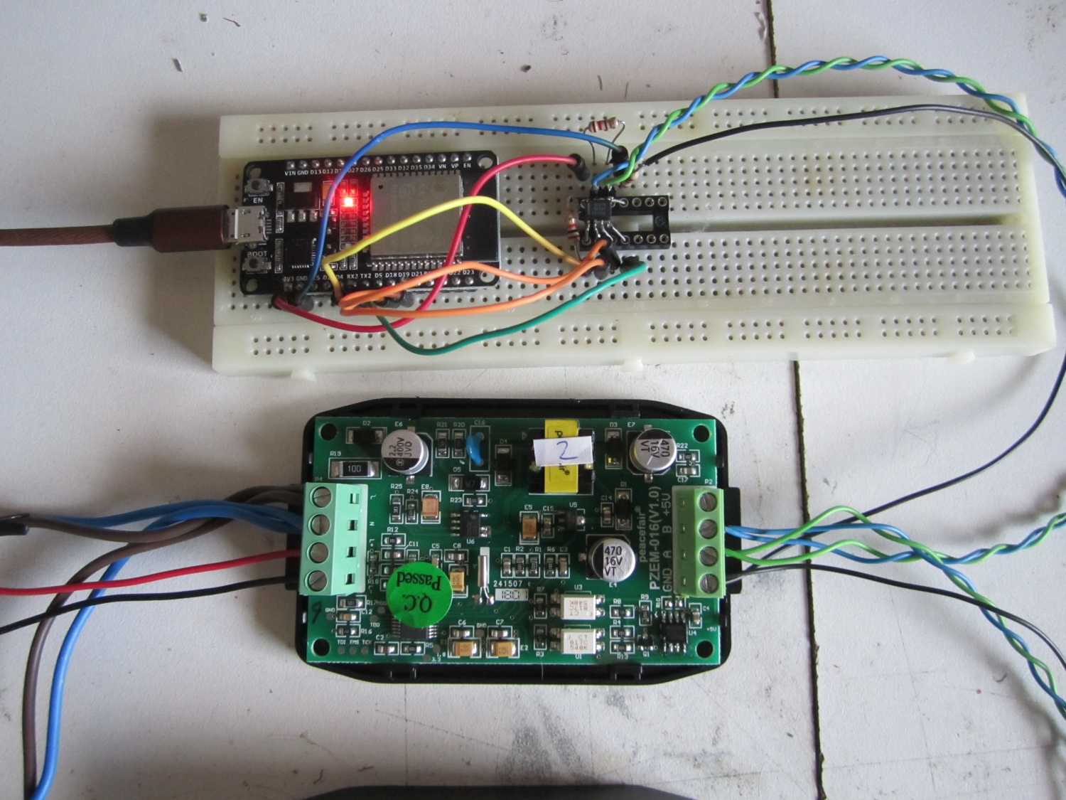
You see in the schematic and the picture the termination resistor on the Rs485 driver in the breadboard. In the PZEM is a build in termination resistor that can’t be easy disabled, you need to solder it out.
I have to test if a setup with 6 PZEM will work if you leave all the resistors, will come back to that if all my ordered PZEM are arrived and tested.
For the wiring of the Rs485 bus you need to use twisted cable, this will prevent interfering of the Rs485 signal by external sources. Read this if you want to know more theory.
And then we have the ground wire for the network. it’s not necessary but my experience is that the network preforms not that good with long wires if you don’t use the ground wire. To prevent unwanted ground loop currents I have added a 100Ω resistor.
That was the hardware, let continue with the software. First we have to edit some files.
If you are going to use uart1 or 2 on the esp32 you have to comment out some lines in esp32-hal-uart.c ;
//uart->dev->conf0.txfifo_rst = 1;
//uart->dev->conf0.txfifo_rst = 0;
//uart->dev->conf0.rxfifo_rst = 1;
//uart->dev->conf0.rxfifo_rst = 0;
If you want to use an easy way to switch between PZEM slaves you can edit the ModbusMaster files.
In ModbusMaster.h you add at blanco line 78;
void slaveid(uint8_t);
In ModbusMaster.cpp you add at blanco line 75;
void ModbusMaster::slaveid(uint8_t slave)
  {
    _u8MBSlave = slave;
  }
If you are going to use the ModMaster library attached to this post, there’s no need to change this, it’s already done.
The Arduino code is commented and should be clear enough to get you going.
In the code there’s a function called changeAddress , with this function you can change the slave address of the PZEM. Preferable you do this the best when only one PZEM is connected to the network. If you do something wrong or forgot the old slave address you can use the broadcast address 0xF8 to reset the address to a known number changeAddress(0xF8, 0x01). When using the broadcast address you must have only one slave connected.
The other function resetEnergy will set the energy counter (Wh) back to zero.
One think that’s a bit strange and is (I think) as misprint in the manual and that’s the order of the crc bytes.
The manual talks about Crc-highbyte first and then Crc-lowbyte. However this doesn’t work and with the help of sniffing the data between the PZEM014-Master software provided by Peacefair and the PZEM I found out that the crc order must be Crc-lowbyte first and then the Crc-highbyte. You can calculate very easy modbus crc here online.
Tested it all with an Esp32, but it should also work with an Esp8266 if you use the software uart and probably it works also with the other Arduino boards.
Note 27/7/2020: If the communication fails and you are using the PZEM-016 for the first time you must set the slave address first. You can do this with the tool provided by manufacturer or with the help of de Arduino code below by enable the line changeAddress and change it to changeAddress(0xF8, 0x01)
Download the Arduino Sketch and the modified ModbusMaster library.
/*
An Arduino Sketch for reading data from a PZEM-014 or PZEM-016, tested with ESP32 DEVKit 1, Arduino 1.8.5
EvertDekker.com 2018
If you want to use slaveid function to change the slaveid on the fly, you need to modify the ModbusMaster library (Or get the copy from my website)
In ModbusMaster.h add at line 78
void slaveid(uint8_t);
In ModbusMaster.cpp add at line 75
void ModbusMaster::slaveid(uint8_t slave)
{
_u8MBSlave = slave;
}
*/
/* If you are using other then uart0 on the ESP32, Comment out in esp32-hal-uart.c the follwing line:
//uart->dev->conf0.txfifo_rst = 1;
//uart->dev->conf0.txfifo_rst = 0;
//uart->dev->conf0.rxfifo_rst = 1;
//uart->dev->conf0.rxfifo_rst = 0;
Source: https://github.com/4-20ma/ModbusMaster/issues/93
*/
#include <ModbusMaster.h>
HardwareSerial Pzemserial(2);
#define RXD2 16 //Gpio pins Serial2
#define TXD2 17
#define MAX485_DE 19 // We're using a MAX485-compatible RS485 Transceiver. The Data Enable and Receiver Enable pins are hooked up as follows:
#define MAX485_RE_NEG 18
ModbusMaster node;
static uint8_t pzemSlaveAddr = 0x01;
void setup() {
Pzemserial.begin(9600, SERIAL_8N1, RXD2, TXD2); // Note the format for setting a serial port is as follows: Serial2.begin(baud-rate, protocol, RX pin, TX pin);
Serial.begin(9600);
node.begin(pzemSlaveAddr, Pzemserial); //Start the Modbusmaster
pinMode(MAX485_RE_NEG, OUTPUT); // Setting up the RS485 transceivers
pinMode(MAX485_DE, OUTPUT);
digitalWrite(MAX485_RE_NEG, 0); // Init in receive mode
digitalWrite(MAX485_DE, 0);
node.preTransmission(preTransmission); // Callbacks allow us to configure the RS485 transceiver correctly
node.postTransmission(postTransmission);
//changeAddress(0x01, 0x02);
/* By Uncomment the function in the above line you can change the slave address from one of the nodes, only need to be done ones. Preverable do this only with 1 slave in the network.
changeAddress(OldAddress, Newaddress)
If you f*ck it up or don't know the new address anymore, you can use the broadcast address 0XF8 as OldAddress to change the slave address. Use this with one slave ONLY in the network.
Note: First run of a new PZEM-016 you have to set the slave address first with: changeAddress(0xF8, 0x01)<br /><br /> */
//resetEnergy(0x01);
/* By Uncomment the function in the above line you can reset the energy counter (Wh) back to zero from one of the slaves.
*/
delay(1000);
}
/*
RegAddr Description Resolution
0x0000 Voltage value 1LSB correspond to 0.1V
0x0001 Current value low 16 bits 1LSB correspond to 0.001A
0x0002 Current value high 16 bits
0x0003 Power value low 16 bits 1LSB correspond to 0.1W
0x0004 Power value high 16 bits
0x0005 Energy value low 16 bits 1LSB correspond to 1Wh
0x0006 Energy value high 16 bits
0x0007 Frequency value 1LSB correspond to 0.1Hz
0x0008 Power factor value 1LSB correspond to 0.01
0x0009 Alarm status 0xFFFF is alarm,0x0000is not alarm
*/
void loop() {
uint8_t result;
for (pzemSlaveAddr = 1; pzemSlaveAddr < 3; pzemSlaveAddr++) { // Loop all the Pzem sensors
node.slaveid(pzemSlaveAddr); //Switch to another slave address. NOTE: You can only use this function is you have modified the ModbusMaster library (Or get the copy from my website)
Serial.print("Pzem Slave ");
Serial.print(pzemSlaveAddr);
Serial.print(": ");
result = node.readInputRegisters(0x0000, 9); //read the 9 registers of the PZEM-014 / 016
if (result == node.ku8MBSuccess)
{
uint32_t tempdouble = 0x00000000;
float voltage = node.getResponseBuffer(0x0000) / 10.0; //get the 16bit value for the voltage, divide it by 10 and cast in the float variable
tempdouble = (node.getResponseBuffer(0x0002) << 16) + node.getResponseBuffer(0x0001); // Get the 2 16bits registers and combine them to an unsigned 32bit
float current = tempdouble / 1000.00; // Divide the unsigned 32bit by 1000 and put in the current float variable
tempdouble = (node.getResponseBuffer(0x0004) << 16) + node.getResponseBuffer(0x0003);
float power = tempdouble / 10.0;
tempdouble = (node.getResponseBuffer(0x0006) << 16) + node.getResponseBuffer(0x0005);
float energy = tempdouble;
float hz = node.getResponseBuffer(0x0007) / 10.0;
float pf = node.getResponseBuffer(0x0008) / 100.00;
Serial.print(voltage, 1); // Print Voltage with 1 decimal
Serial.print("V ");
Serial.print(hz, 1);
Serial.print("Hz ");
Serial.print(current, 3);
Serial.print("A ");
Serial.print(power, 1);
Serial.print("W ");
Serial.print(pf, 2);
Serial.print("pf ");
Serial.print(energy, 0);
Serial.print("Wh ");
Serial.println();
} else
{
Serial.println("Failed to read modbus");
}
delay(1000);
}
}
void preTransmission() // Put RS485 Transceiver in transmit mode
{
digitalWrite(MAX485_RE_NEG, 1);
digitalWrite(MAX485_DE, 1);
delay(1);
}
void postTransmission() // Put RS485 Transceiver back in receive mode (default mode)
{
delay(3);
digitalWrite(MAX485_RE_NEG, 0);
digitalWrite(MAX485_DE, 0);
}
void resetEnergy(uint8_t slaveAddr) //Reset the slave's energy counter
{
uint16_t u16CRC = 0xFFFF;
static uint8_t resetCommand = 0x42;
u16CRC = crc16_update(u16CRC, slaveAddr);
u16CRC = crc16_update(u16CRC, resetCommand);
Serial.println("Resetting Energy");
preTransmission();
Pzemserial.write(slaveAddr);
Pzemserial.write(resetCommand);
Pzemserial.write(lowByte(u16CRC));
Pzemserial.write(highByte(u16CRC));
delay(10);
postTransmission();
delay(100);
while (Pzemserial.available()) { // Prints the response from the Pzem, do something with it if you like
Serial.print(char(Pzemserial.read()), HEX);
Serial.print(" ");
}
}
void changeAddress(uint8_t OldslaveAddr, uint8_t NewslaveAddr) //Change the slave address of a node
{
static uint8_t SlaveParameter = 0x06;
static uint16_t registerAddress = 0x0002; // Register address to be changed
uint16_t u16CRC = 0xFFFF;
u16CRC = crc16_update(u16CRC, OldslaveAddr); // Calculate the crc16 over the 6bytes to be send
u16CRC = crc16_update(u16CRC, SlaveParameter);
u16CRC = crc16_update(u16CRC, highByte(registerAddress));
u16CRC = crc16_update(u16CRC, lowByte(registerAddress));
u16CRC = crc16_update(u16CRC, highByte(NewslaveAddr));
u16CRC = crc16_update(u16CRC, lowByte(NewslaveAddr));
Serial.println("Change Slave Address");
preTransmission();
Pzemserial.write(OldslaveAddr);
Pzemserial.write(SlaveParameter);
Pzemserial.write(highByte(registerAddress));
Pzemserial.write(lowByte(registerAddress));
Pzemserial.write(highByte(NewslaveAddr));
Pzemserial.write(lowByte(NewslaveAddr));
Pzemserial.write(lowByte(u16CRC));
Pzemserial.write(highByte(u16CRC));
delay(10);
postTransmission();
delay(100);
while (Pzemserial.available()) { // Prints the response from the Pzem, do something with it if you like
Serial.print(char(Pzemserial.read()), HEX);
Serial.print(" ");
}
}


