EWelink touch hack
This time a hack on the EWelink wifi touch switch.
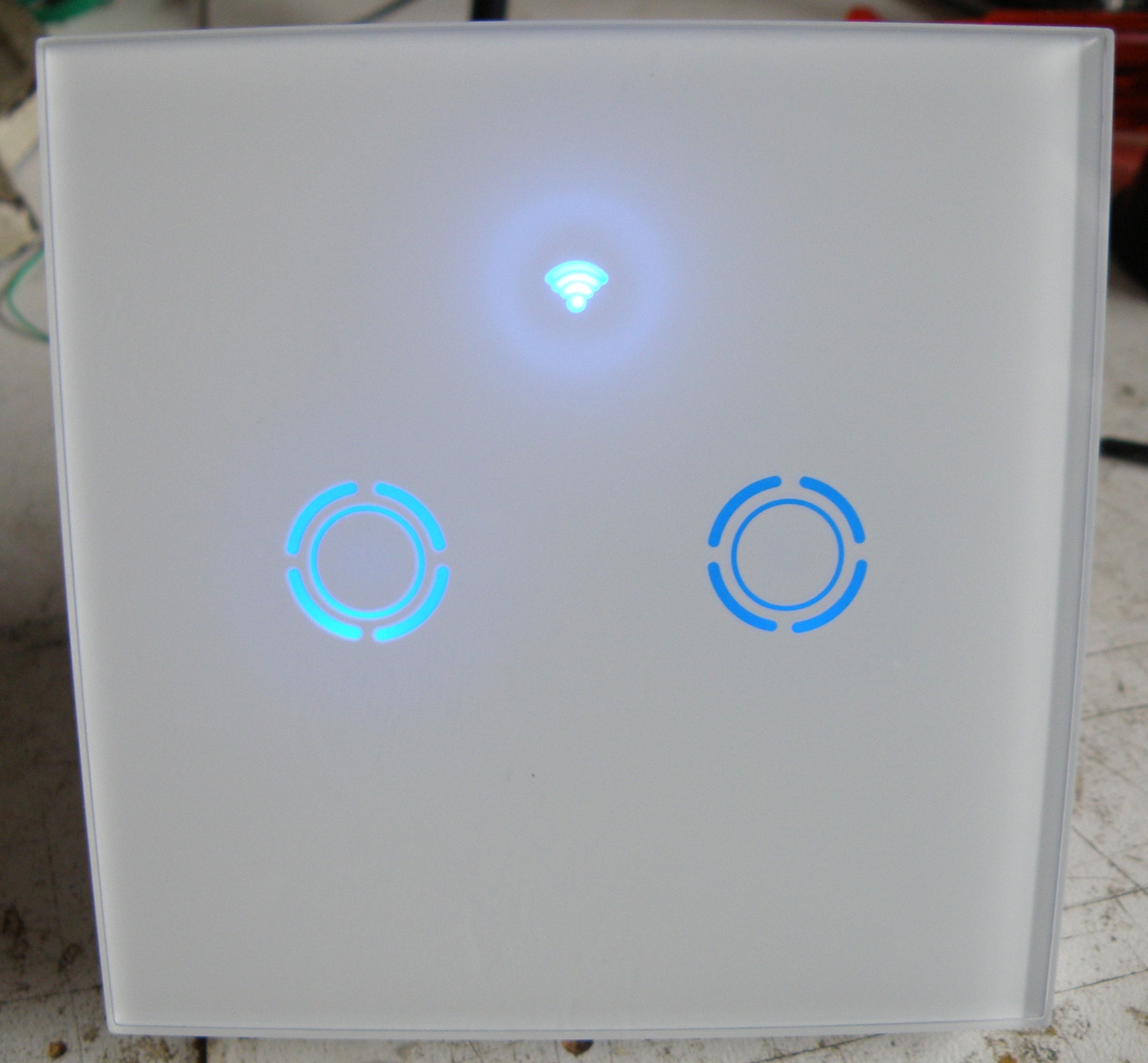
The EWelink touch switch is a similar product as the Sonoff touch, but I find the look a bit nicer. It’s more streamlined and is also available with black front.
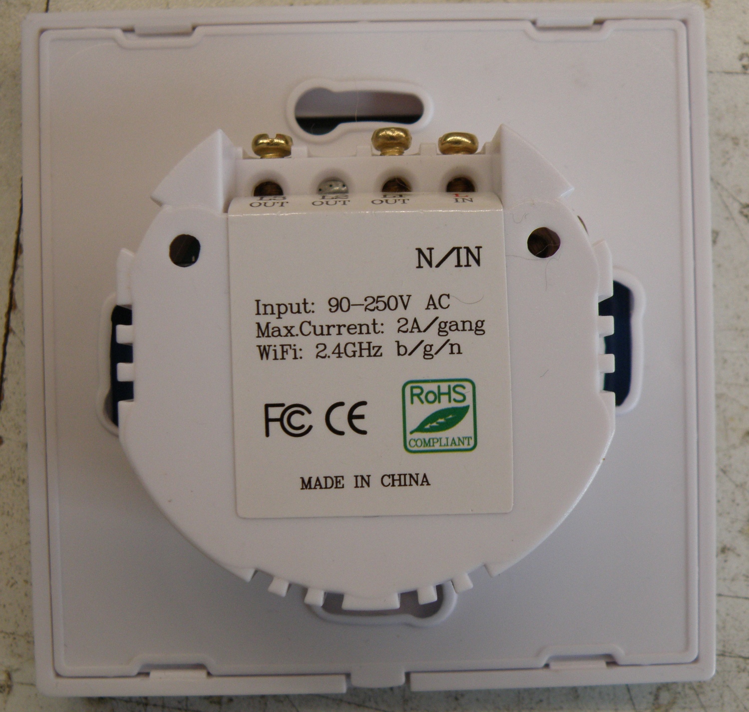
The EWelink is sold in 1,2 and 3 gang version for the EU and US market.
I had only the 2 gang EU version, but it looks to me that the 1,2 and 3 gang EU version are the same. They left some parts out, but the pcb’s are all the same.
Can’t say anything about the US version, don’t have one to take apart.
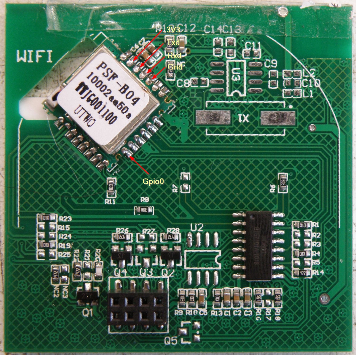
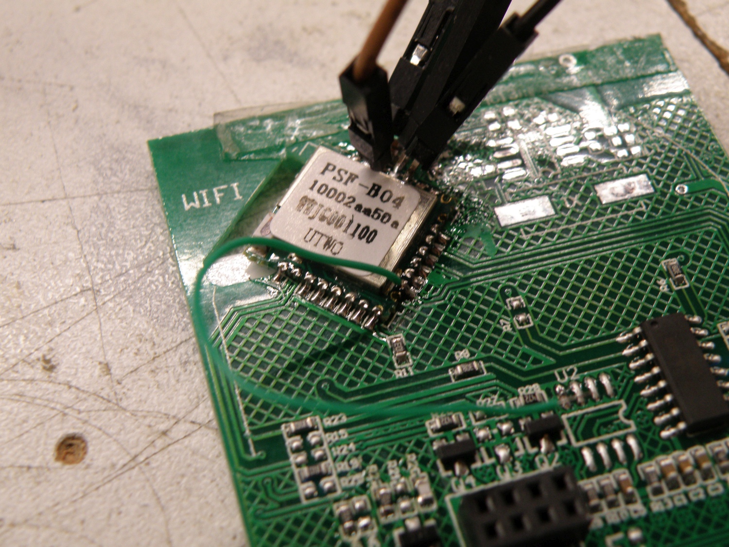
The hart of the EWelink touch switch is the PSF-B04 module. This module contains inside the well know ESP8285, that’s in fact an ESP8266 with build in 1M flash memory.
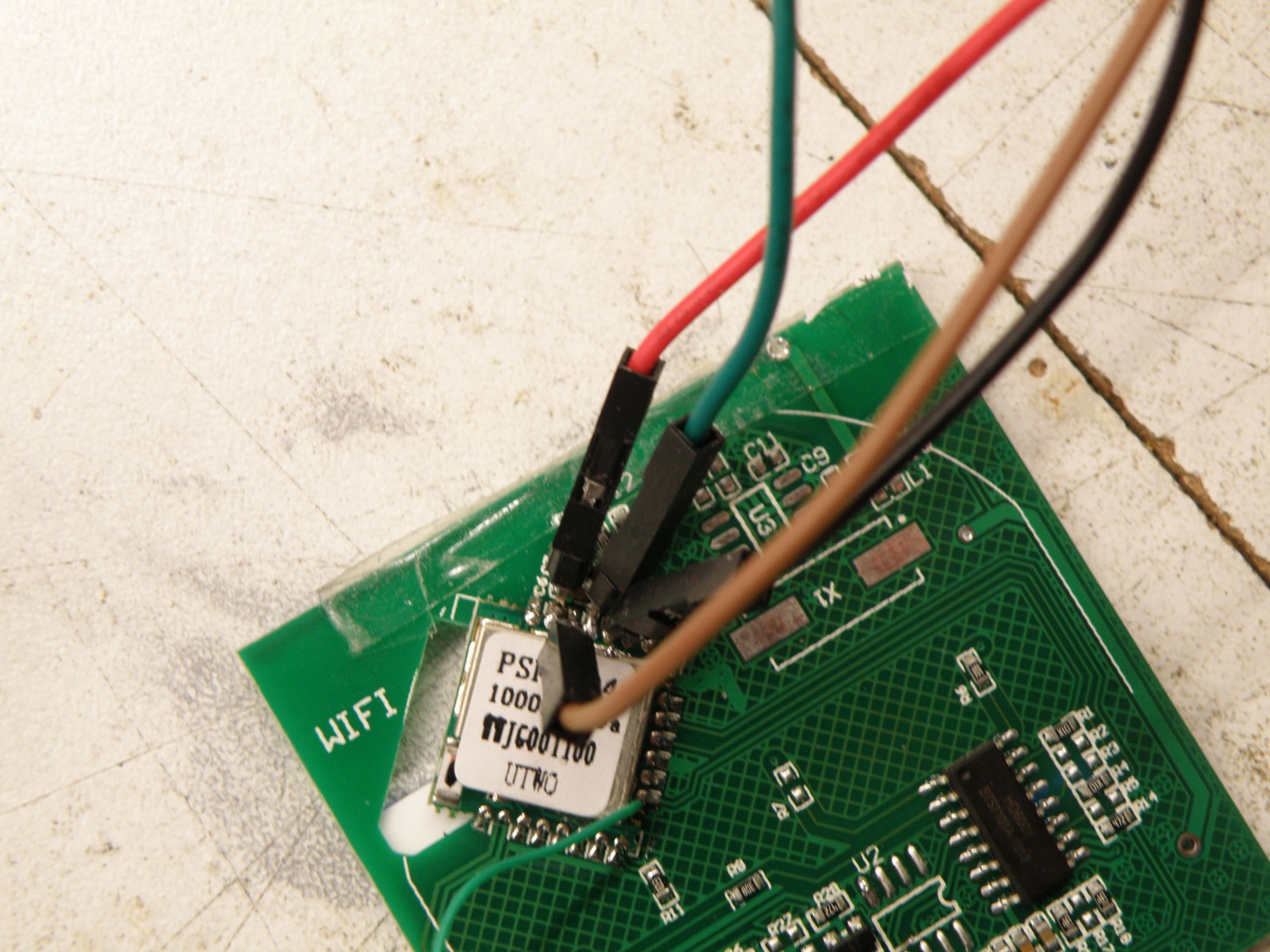
Just like the hacks for the Sonoff products we need to connect Txd, Rxd, Vcc, Gnd and Gpio0 to the touch switch to make it possible to upload our own firmware.
Bummer, EWelink didn’t provide us just like Sonoff with a header where most of the pins required are easy accessible.
Time to get the soldering iron and solder some header pins direct to the PSF-B04 module. Because you can’t and won’t program the touch pcb when it’s connected to the power pcb, you need to provide it also with 3.3V power.
For the Gpio0 a simple wire will do the trick to get the ESP8285 in programming mode.
Pin mapping:
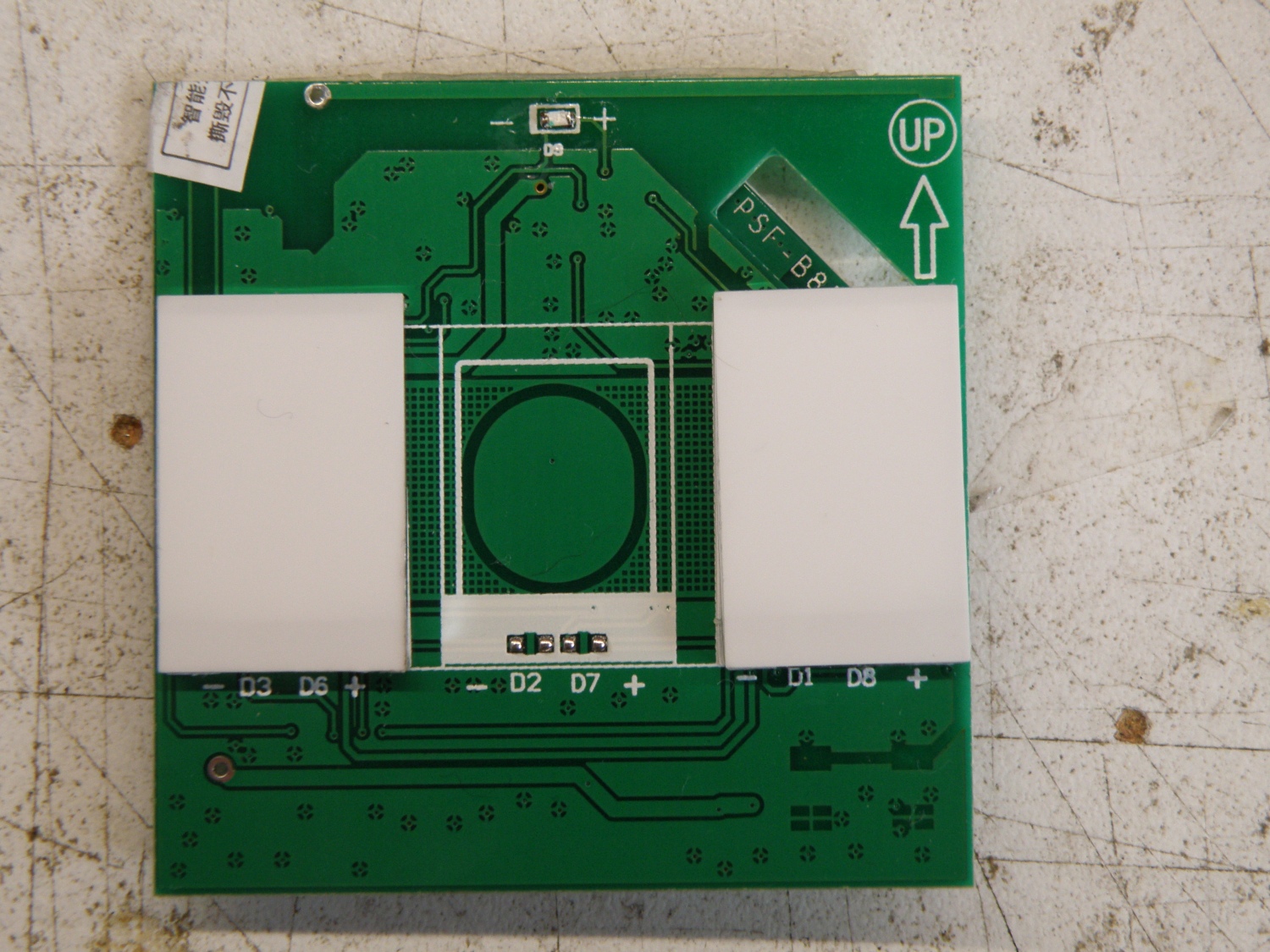
| Wifi Led | Gpio-13 |
| Touch input | Relay + led | |
| left | Gpio-0 | Gpio-12 |
| middle | Gpio-10 | Gpio-4 |
| right | Gpio-9 | Gpio-5 |
The 1 gang uses the middle touch sensor, the 2 gang uses the left and right touch sensor and the 3 gang uses them all.
Note:It looks to me now that they place some resistors in other places for the 1,2 and 3 gang. Think they do that for example so touch1 is always connected to gpio0, but in the 1gang touch1 is in the middle and for the 2 gang the touch is at the left . Can’t verify this because I only have the 2 gang.
Arduino ide settings:
Generic Esp8285 Module
CPU Frequency: 80MHz
Flash Size: 1M (64K SPIFFS)
Upload Speed: 115200
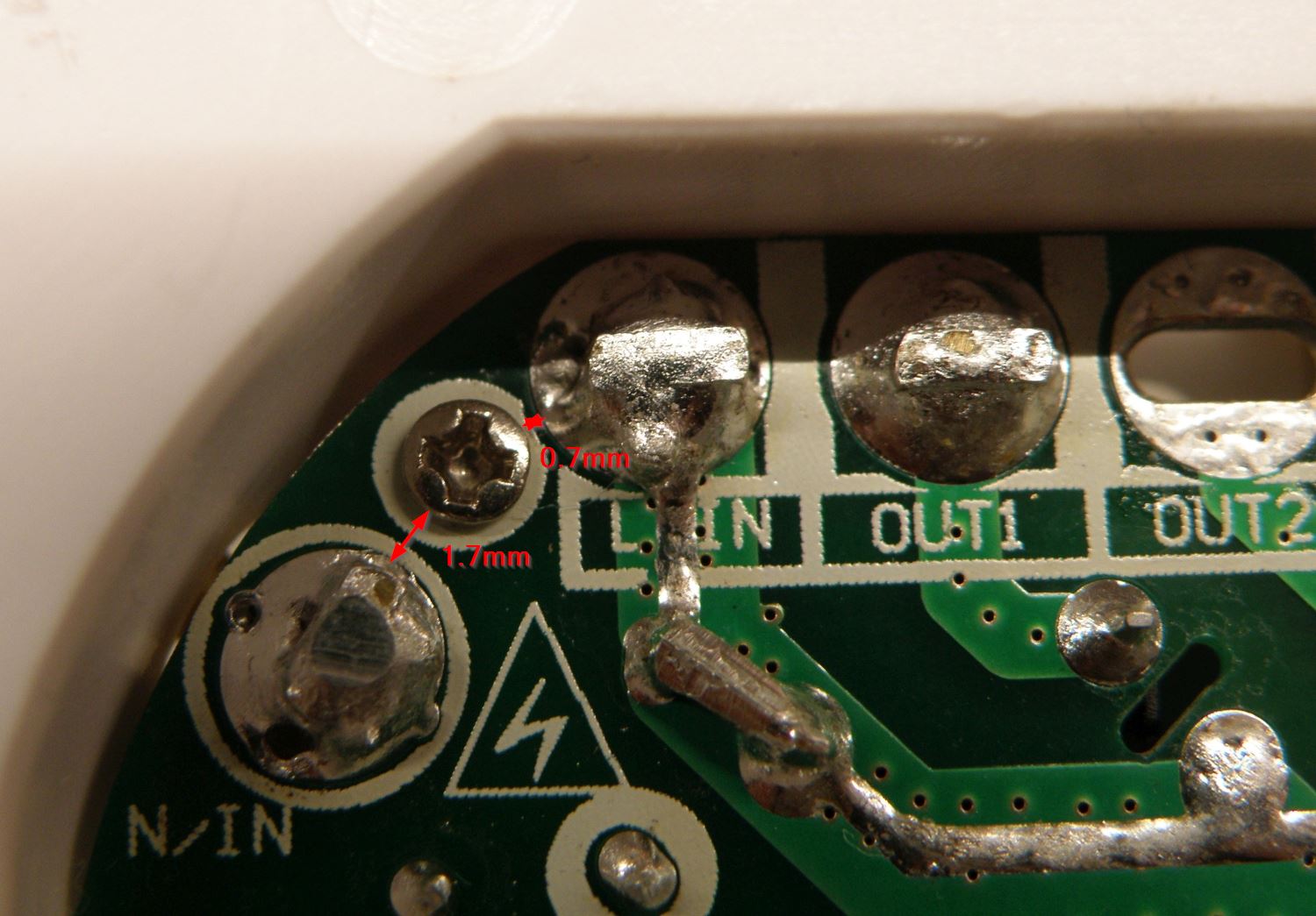
Important Note: As you can see in the last picture below they have placed a screw between the fase (L) and neutral (N) to hold the power pcb in place. The screw makes the isolation distance between the L and N to narrow. The minimum isolation distance requirement for 230V~ is 2.5mm and preferable >3mm. With my Ewelink is was total 2.4mm, that’s not enough.
Simple solution, remove the screw, it doesn’t do anything. The power pcb can’t move because of the screw terminals and the other screws.
Do this all at your own risk.
