Sonoff Slampher V2.0
The Sonoff Slampher is a very interesting product for you domotica project if you don’t want to be to invasive in your electric system.
Factory default the Slampher has some descent software with a nice app, but if you want more for example connect is to your Mqtt broker you need to change the firmware.
If you want to program your own software or other software the can be found on the internet then you have to reprogram the ESP8285 inside
There are enough tutorials on the net how to reprogram the Slampher, however the Slampher that I bought on Ali Express is a new V2.0.
This version has an ESP8285 on board in staid of the famous ESP8266. The ESP8285 is ruffly the same as the ESP8266 except that it has an build in 1MByte flash memory.
With the Arduino ide the ESP8285 can also be programmed, luckily
Lets start;
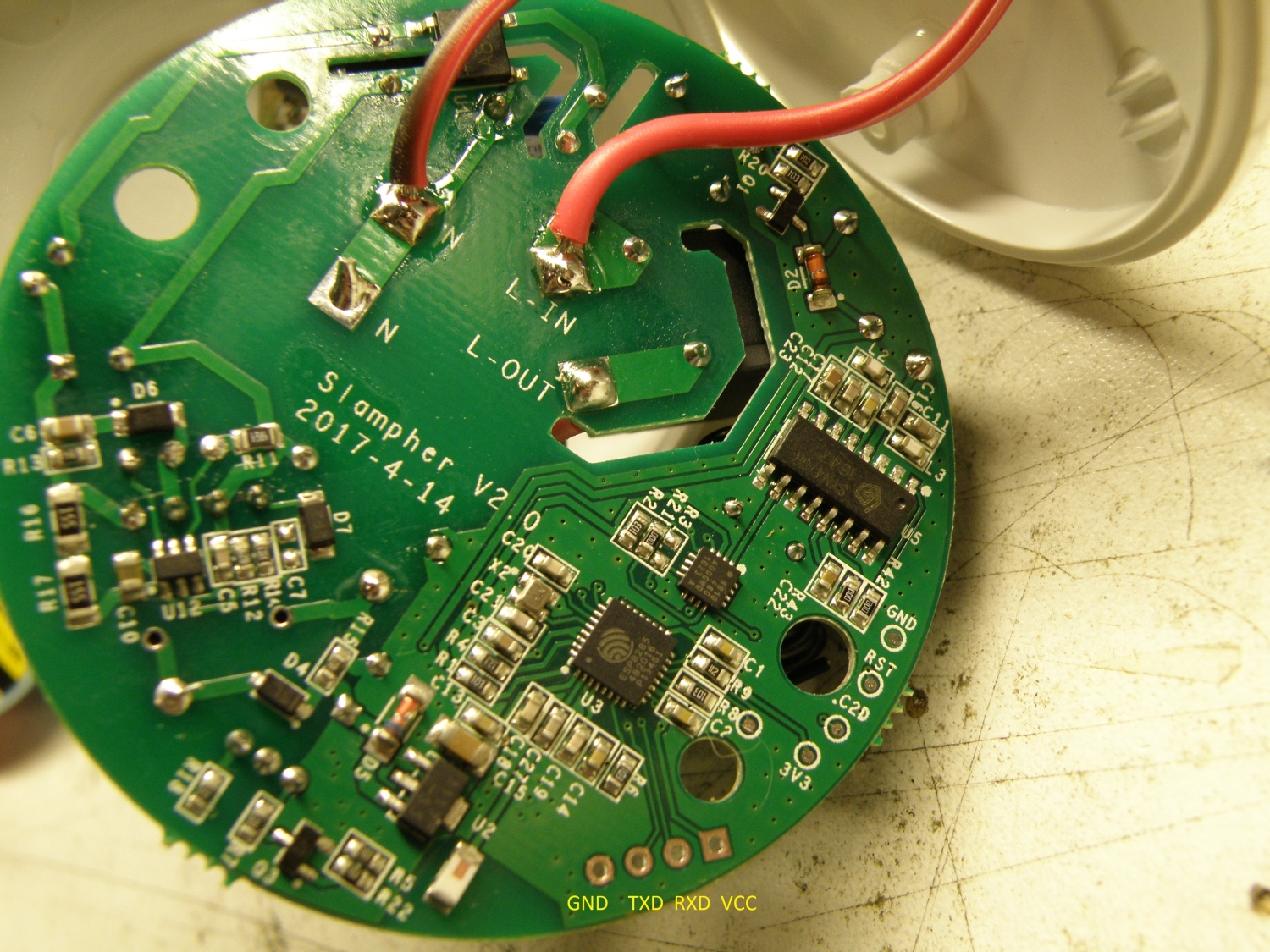
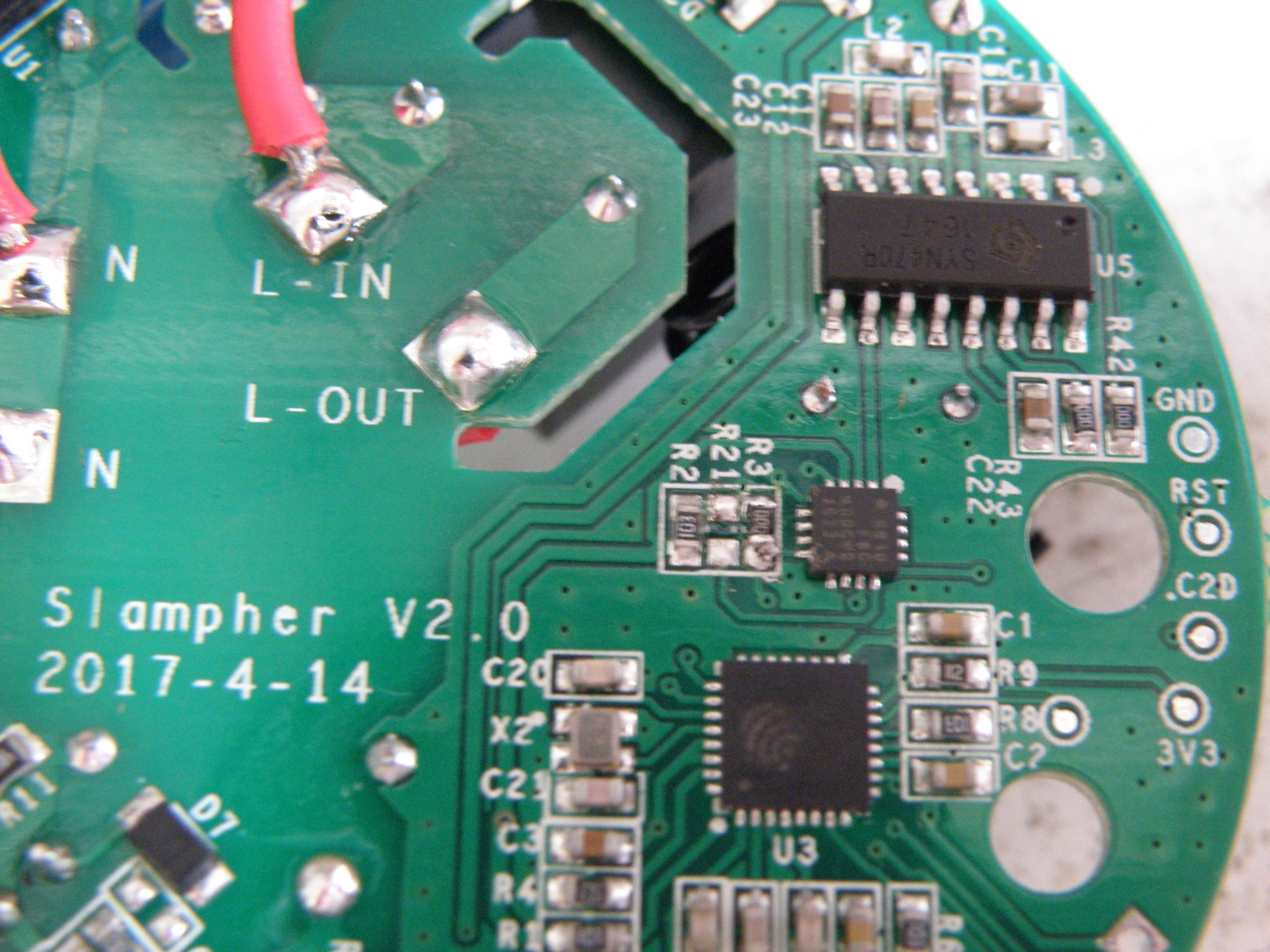
To get the ESP8285 in flash mode we need to connect GPIO0 to the ground. To connect the button on the Slampher to GPIO0 we need to move a resistor. Normally the button is connect to the RF part to learn the Slampher the rf remote. We want to program the ESP8285 and for that move R21 to R3. It’s an 0Ω resistor so a piece of wire or solder will also do the job.
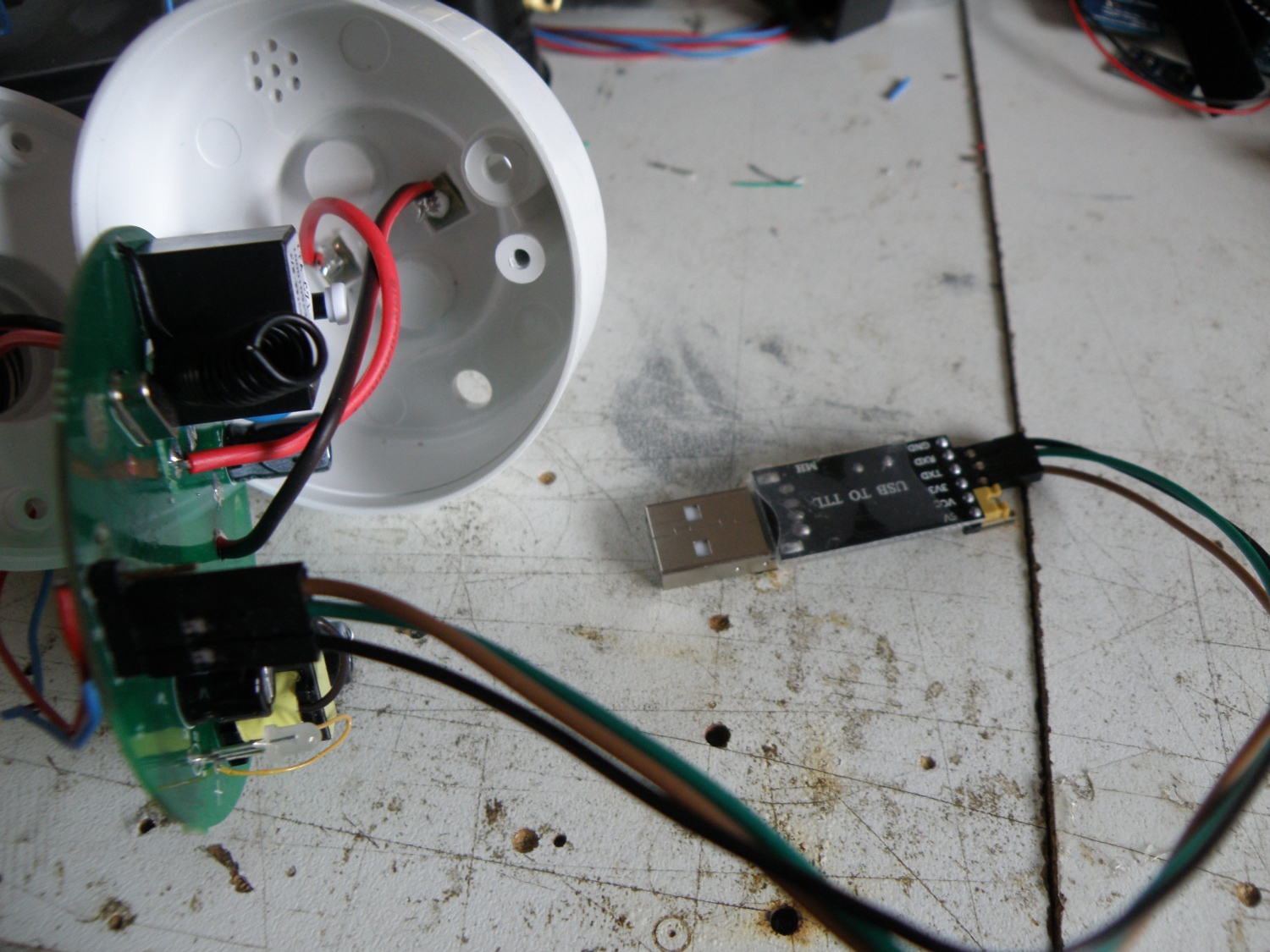
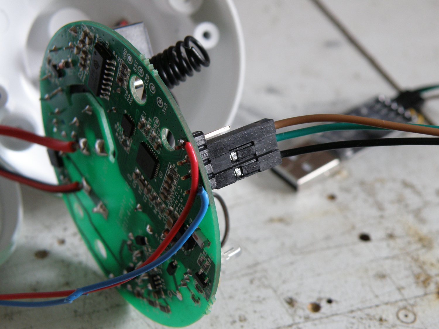
After that you need to connect your usb to serial convertor. Pin 1: Vcc, 2:rxd, 3:txd and 4:gnd . The ESPxx works on 3V3 so don’t fry it with the 5V output of your convertor.
My convertor didn’t have enough mA to supply the Slampher direct so that’s why you see on the pictures a separate 3V3 power supply.
Press the button and insert the usb convertor in your computer and happy flashing.
Don’t connect the Slampher to the mains for your safety.
Personally I add to all my ESPxx programs the OTA (over the air) flash capability’s so you can remove the usb to serial convertor and close up the housing for safety purpose and flash new firmware ota.
The relay won’t work if you not connect the Slampher to the mains, it needs the 5V from the transformer.
Here is a small sample on GitHub to get is working, button, relay, ledgreen are supported. Ledred and the rf receiver are not (yet) supported.
Arduino ide settings:
Gerneric Esp8285 Module
CPU Frequency: 80MHz
Flash Size: 1M (64K SPIFFS)
Upload Speed: 115200


Thanks a lot for your explanation, I receive my sonoff slampher one week ago and I was turning in round just to find the proper way to flash it.
Just a question, the Gthub software is espeasy or another one?
Thanks
Hi,
The software on my github is a very simple example to test the relay and led.
Forgive a noob question, but when you say “move R21 to R3. It’s an 0Ω resistor so a piece of wire or solder will also do the job,” are you meaning to solder a wire from one to the other, or just creating continuity between the two while connecting a serial converter?
Hi,
You can permanently move the resistor from R21 to R3, there’s no need to place it back.
Hello,
do you happen to have the full schematics? Furthermore, if you move the resistor from R21, will you loose any functionality? For example, will the button/RF part work correctly? Is it possible to temporarily short-circuit R3 without removing R21?
Thanks in advance
Hi,
No, Sorry but I don’t have the full schematic.
If you remove R21 then indeed the rf button won’t work anymore. I don’t have the rf version to test, but I think it’s not a problem to place them both.
You can also solder a wire to the R3 pad (this is connected to GPIO0) that’s close to the ESP8285 and hold this wire to the GND to get the ESP in download mode.
Hi, I’m wondering if you can use the gpio0 to wire a rocker switch to the board and use that as an input for the switch itself. I’d like to put this inside the wiring box behind my wall switch. Did you figure out the location of any GPIOs?
Hi,
You can connect a switch to gpio0 that shouldn’t be a problem.
The ESP8285 have enough spare GPIO available, however Sonoff didn’t make them accessibly easy for us.
You can use for example GPIO5 that can be found at pin 24.
It’s not that easy to solder a wire to but much easier then a pin in the middle.
Thanks for the article! I was able to flash my Slampher after that
One question though:
As adviced in the article I moved R21 to R3. Now I’m able to flash the firmware, but at random moments in time the relay is triggered. Based on my firmware’s logs, it receives a signal on GPIO 0 that the button was been pressed.
I’m pretty sure that it’s not a software bug, as exactly the same one (same build actually) runs on my other Sonoff S20 sockets which don’t have this problem.
I noticed however that usually the “button press” is received at night or very early in the morning. I live in a 4-storey building and there’re smaller houses with garages nearby. It may happen that someone uses an RF remote control to control the garage when leaves early in the morning or comes back late at night.
So the question is: is it in theory possible that moving R21 to R3 could cause the RF receiver to issue a signal to GPIO 0 whenever an RF signal is received (even though, my Slampher hasn’t been paired to any RF controller)?
Hi Max,
Yes, I think the RF receiver can do something with GPIO0.
I don’t have a schematic from the V2.0 slampher, however looking at the V0.2 schematic and the V2.0 pcb this is what I think is the problem;
On the right of the pcb you see a “big” chip (U5), the SYN470R. This is the RF receiver and this will output his data on pin10 to the EFM8BB10F (U4?, is not on the silk screen). This EFM8BB10F is an 8051 based micro controller and responsible for decoding and learning the RF code.
The EFM8BB10F will decode the received RF data coming from the SYN470R and will send, if the remote control matches, something to the ESP8285, it’s not exactly clear looking at the pcb how this is done.
However pin10 of the EFM8BB10F is also connect to GPIO0 of the ESP8285, so this confirms that it is possible that RF can do something with GPIO0.
How to get rid of the problem?, there are 3 possible solutions that I think will work. Note: It’s all at your own risk.
I think the easiest way is lifting pin10 of the SYN470R from the pcb (or cut the trace coming from pin 10), this will prevent that received data is send to the EFM8BB10F.
Or you can completely remove the EFM8BB10F from the pcb, this requires a hot air gun and some soldering skills.
And last but also a difficult solution is to cut the trace between pin10 of the EFM8BB10F and the bottom pad of R3.
Have fun, let me know if this solved your problems.
Hi Evert, thanks a lot for your answer and sorry for taking so long to respond!
The issue is fixed. Although I cannot say for sure what was the problem, cause I did 2 things at the same time – I cut pin 10 as you suggested, but then I also noticed that while moving R21 to R3 I accidentally made a tiny, almost invisible contact between R21 and R3 contacts (on the side which is closer to ESP). So I made sure there’s no contact as well.
Now I don’t have any false GPIO0 signals anymore (confirmed after a month of usage)
Max, I dont think it’s because the resistor was moved. I’m currently searching on how to re-program my slampher and found this article. I wanted to reprogram it due to the very same issue you have. My Stock standard un modified Slampher V2 is doing the same. It randomly triggers the relay. I thought if I could re-program it with the WEMO emulator to work better with my amazon echo. But it seems like it wont solve my problem. My normal sonoff basic does not suffer from this issue. Usually this kind of problem is related to a floating IO pin that has a dry contact. Cant say for sure if its ineed a dry contact or a bug in the design.
Thank you very much for your information. it helped me to flash my slampher v2.0 to my own sketch via arduino ide.
I was a little confused about your “Connect Usb to Serial” Picture (Nr.3( . it looked to me, that you had connected the 3.3V port not the ground to the slampher.
THANK YOU !!!
Dear Evert,
I had follow your tutorial step by step but unfortunately still not works with me before I had tried more times… I always get this error: espcomm_open failed… please help
“espcomm_open failed” is a general error, it’s hard to say what’s going wrong.
If you have modified the resistor according my blog, then you have hold the button during powering up the Sonoff, after that it should be possible to flash the Sonoff. If you still get the error, try swapping rxd and txd.