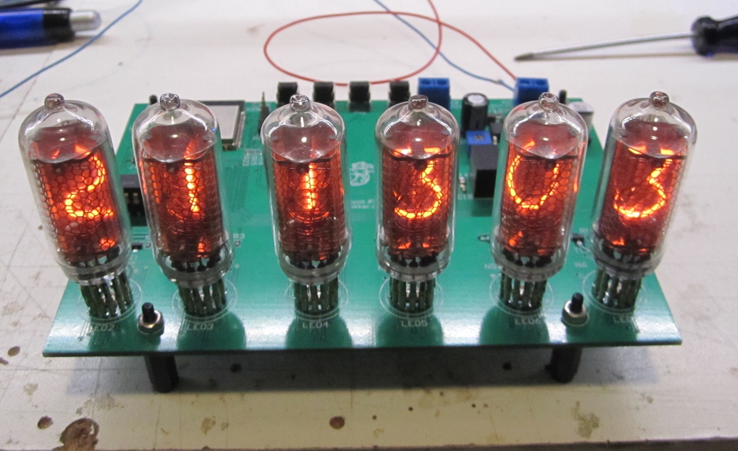
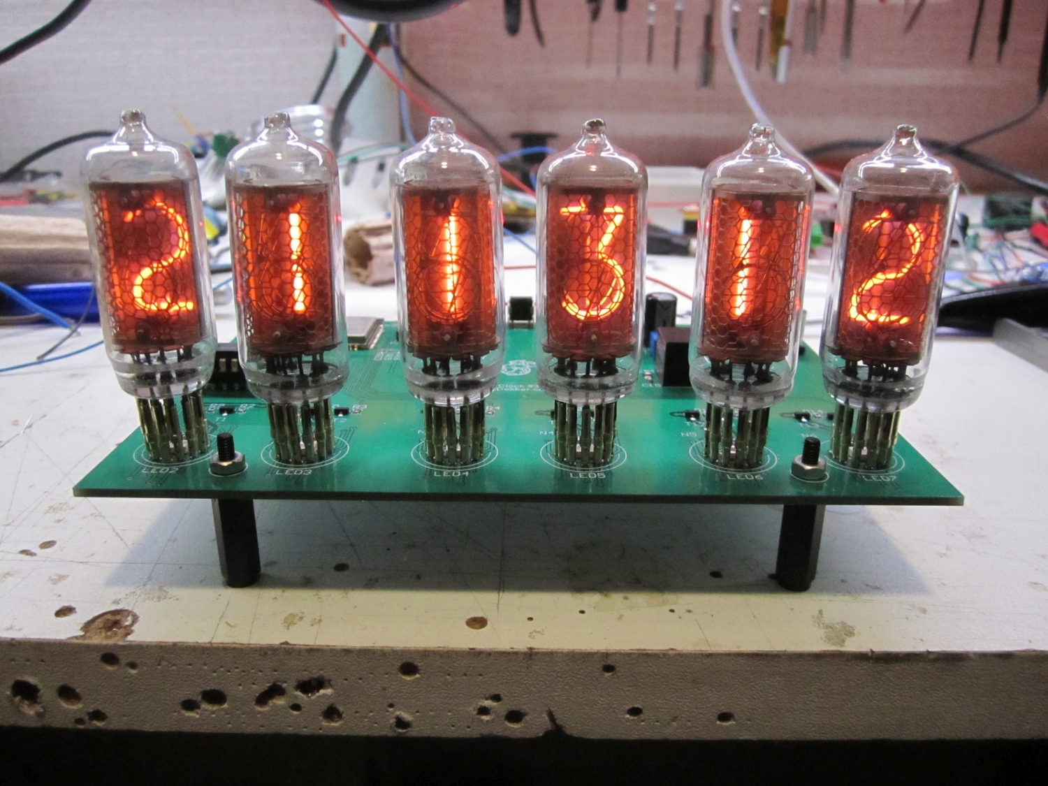
Nixie Clock #3
After my Nixie clock #1 and Nixie clock #2 it was now time for #3.
I still had laying around some IN-8 tubes that I bought a couple of years ago by mistake. The plan was to order IN8-2 tubes as spare for my Nixie #1 clock, but for some reason I didn’t read the specs good enough from the e-bay seller.
Nixie clock #1 did get his time update over the Joshua domotica network from the Tcp/ip gateway. This works perfect, however for the new design a stand alone time update would be nice, so no gateway but direct over wifi to a ntp server.
To accomplish this I was thinking about an Esp82666 or Esp32. The Esp8266 in the form of an Esp12 didn’t had enough gpio pins, so the Esp32 was the winner.
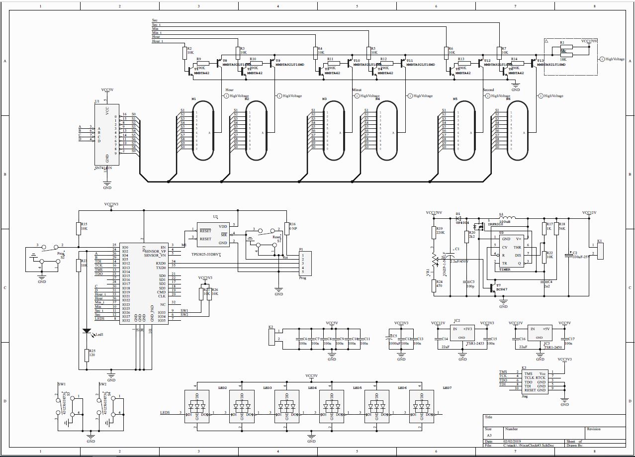
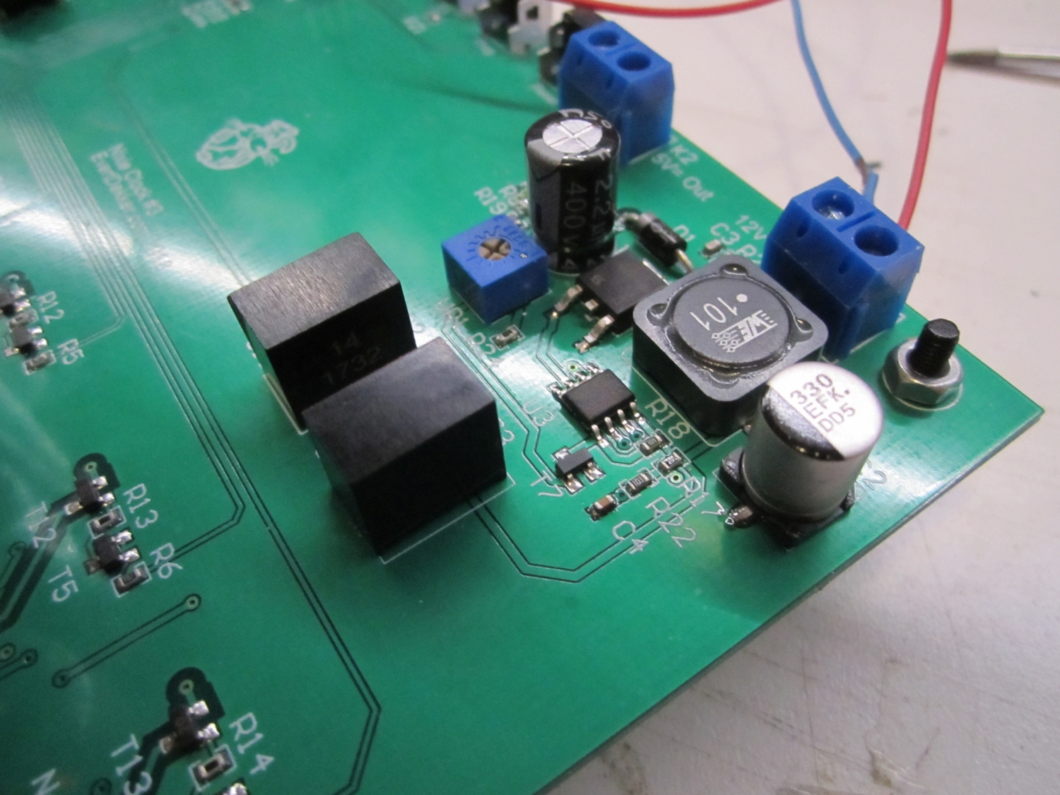
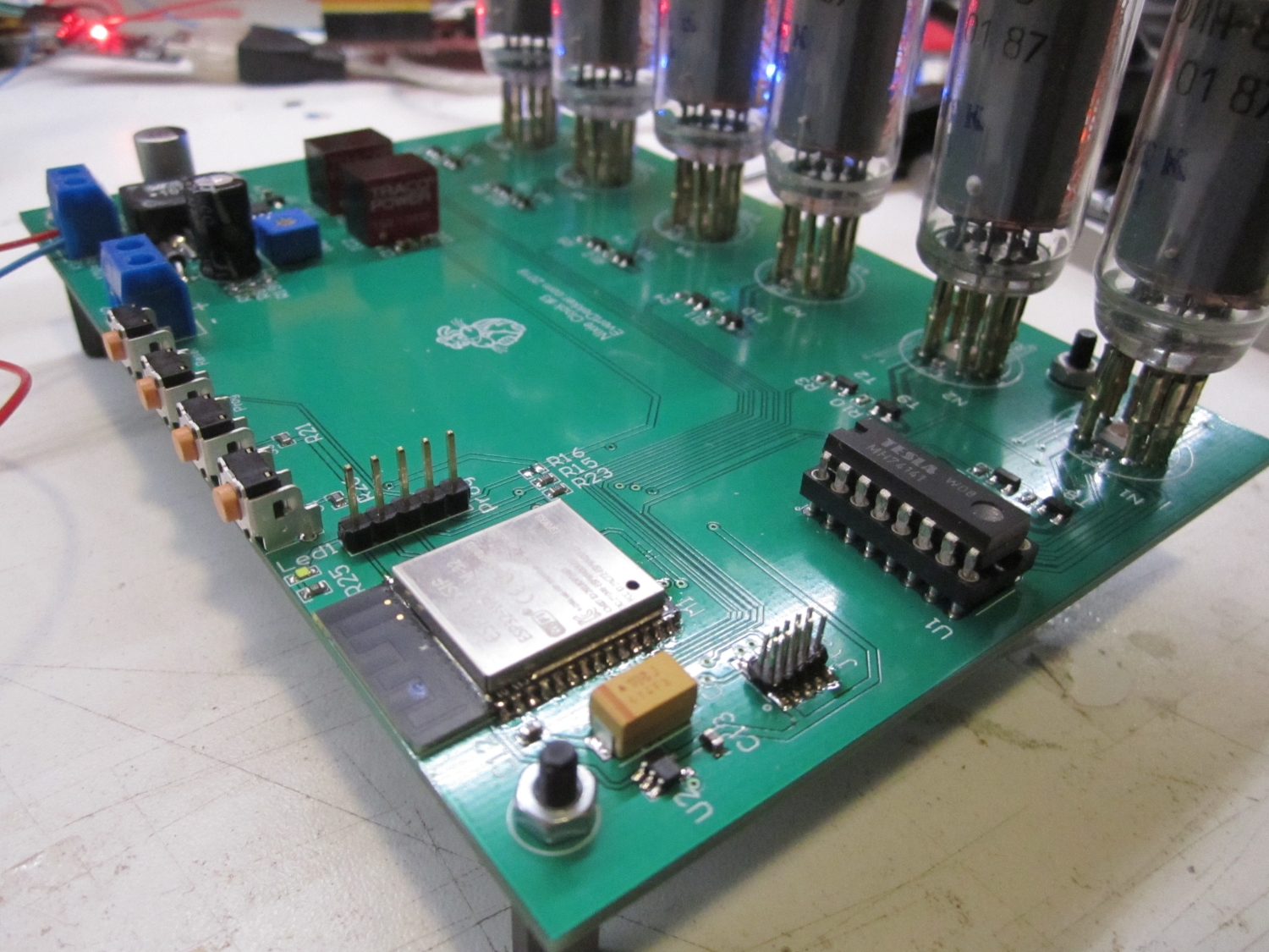
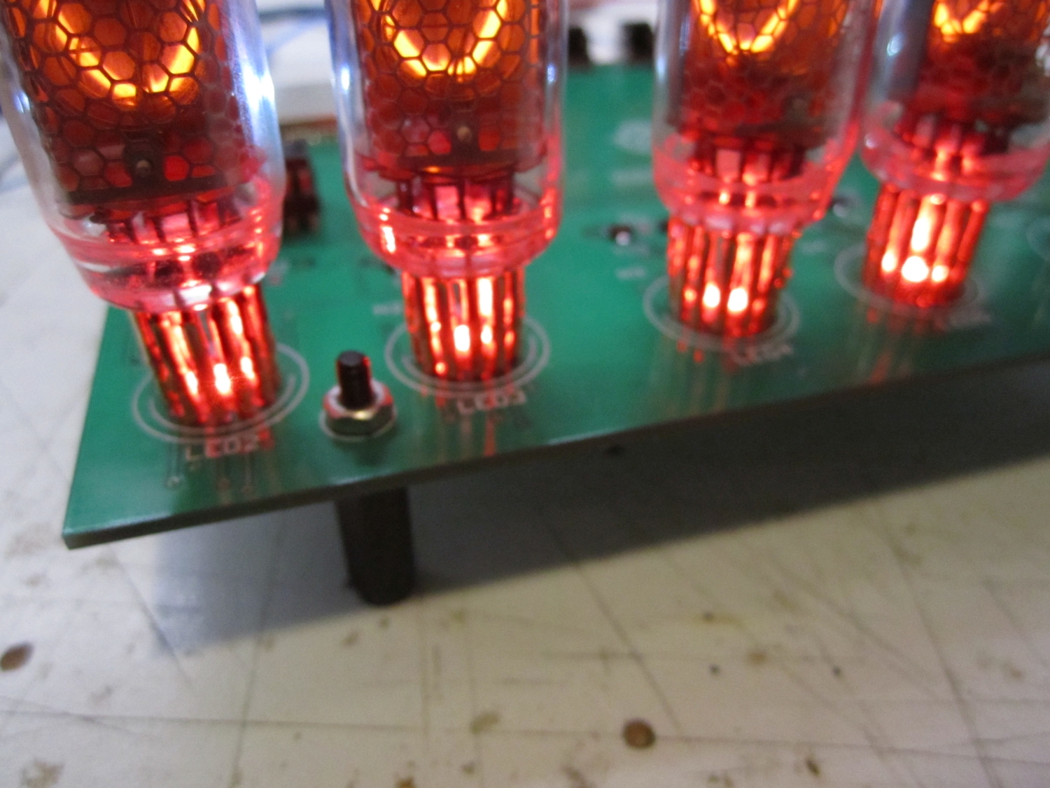
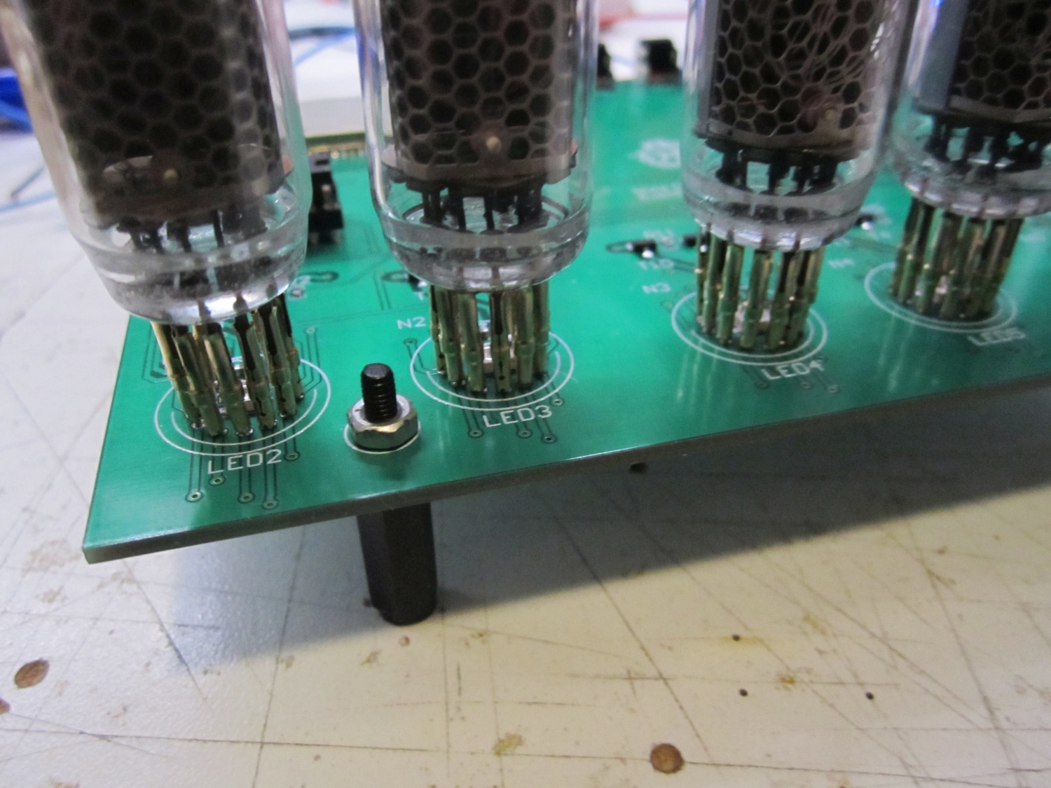
Major parts of the schematic is recycled from my first 2 nixie clocks. High voltage power supply, multiplexer and anode drivers are kept the same. The foot led lighting (I know some of you guys hate it) are this time rgb and to save some IO pins they are from the daisy chain type, the SK6812 in 3.5×3.5mm package. These leds requires 5V and the Esp32 requires 3.3V, so for these voltages I used ready made Tracopower switching step down regulators.
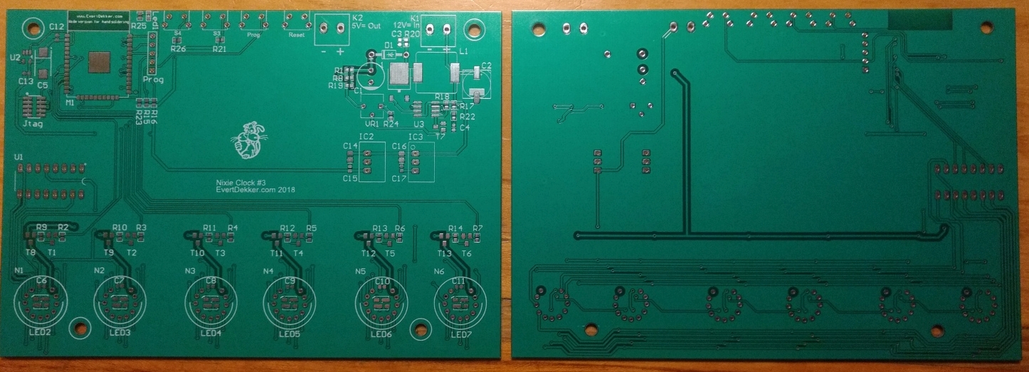
Pcb was designed in Altium and made by Elecrow. The design of the pcb is so that it will fit in the (old) enclosure of my Nixie clock #1, that’s why the pcb is for the biggest part empty.
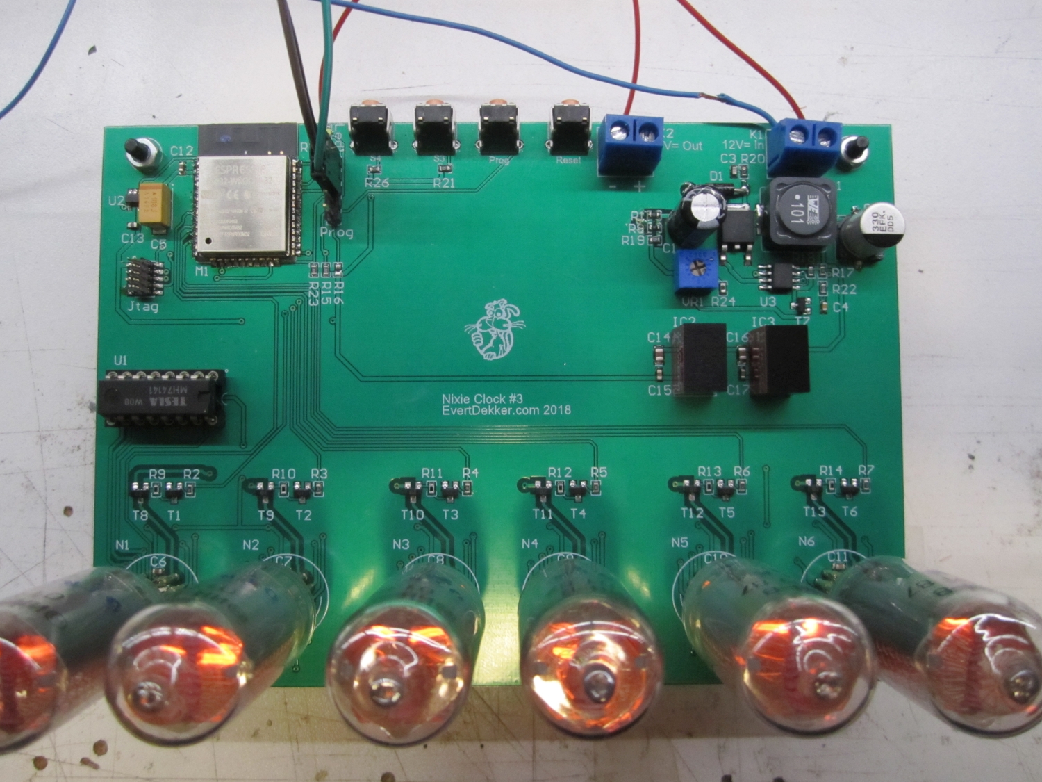
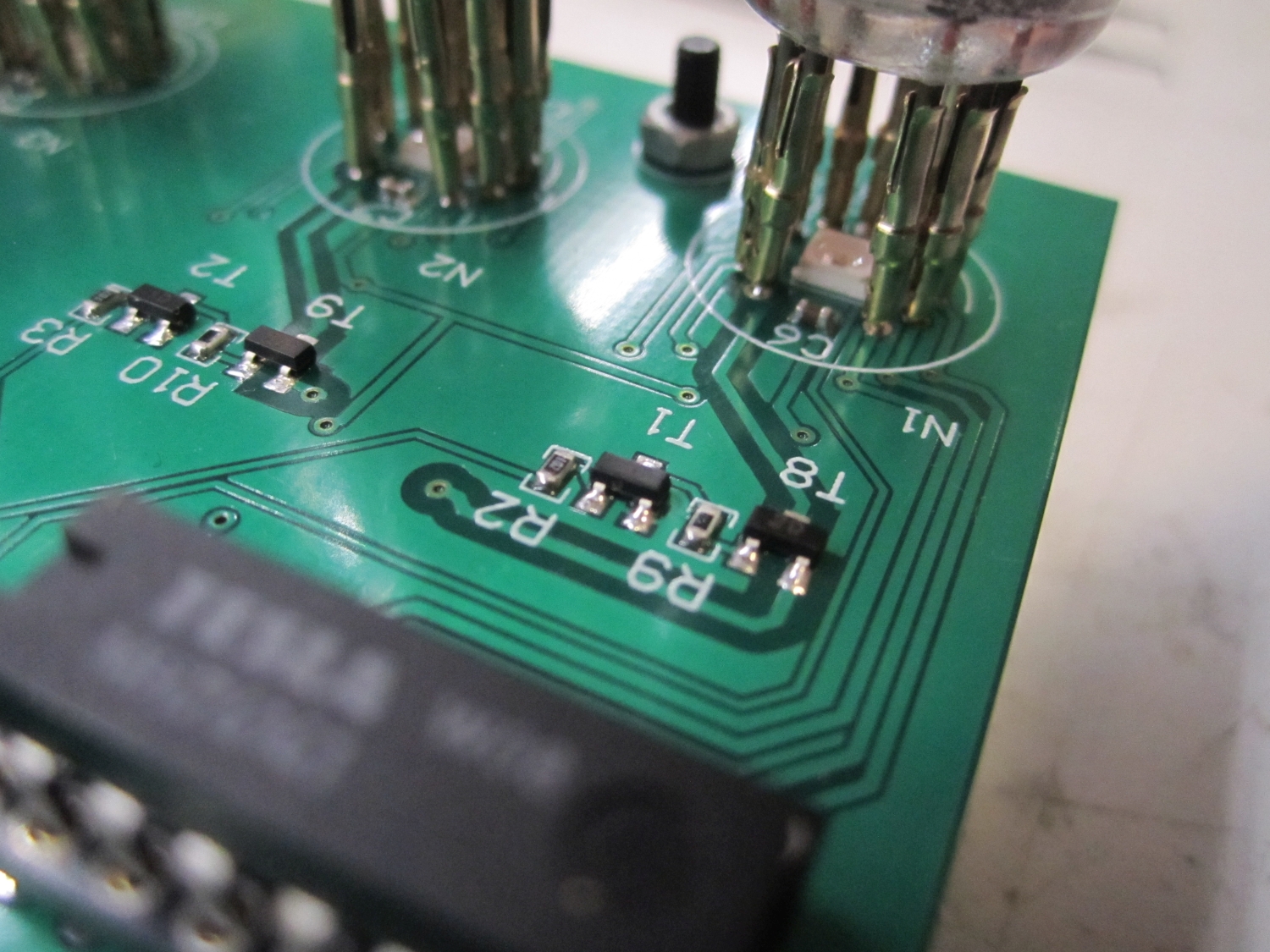
Assembling the board was not that hard except for the SK6812 leds. Due the poor mechanical structure of the chip is hard to solder them. Hand soldering is not possible, even with the heat gun it was difficult because the melting point of the plastic was close to the melting point of the solder. I managed to get it done by applying solder paste to the pcb, preheated the board from the bottom with a pre-heater and finished the soldering with the heat gun. Working fast was a must, but due the preheating the time that the air gun needed to be hold on the led was very short.
The nixietubes are mounted in socket for easy replacement and mounting.
The software was written with the help of the Arduino ide and Esp32 core. Because the ESP32 doesn’t have a PORT like the Atmel cpu’s is harder to control the rows and columns. Normally you send the digit to the port and with the help of a mask the BCD to decimal decoder it’s easy to set pins from a port according the values for the digit. For the Esp32 it was necessary to control every pin individuality with DigitalWrite, have a look at code to see want I meant and how it’s done.
Multiplexing the tubes is better for the lifetime and easier for the power supply etc. Multiplexing the tubes with an interval of 2ms gave the best result, you don’t see the tubes flickering and they still give enough light. The Esp32 runs on FreeRtos the idea was to use a separate task for multiplexing and updating the tubes. It looked that this was working fine wasn’t it that it looks that sometime one of the tubes gave some more light. Measuring with the scope on the base of on of the drivers confirmed me that sometimes the interval wasn’t 2ms but 3ms. I tried almost everything, high priority, more stack etc. but the problem stays.
Time to go back to the drawing board and start over with the multiplex part of the code. This time I have used a hardware timer to update the display every 2ms so far it works flawless.
Last problem that need to be solved was that the time server was not working, at least not the provided sample from the Arduino ide. After some reading and experiments I noticed that is was working when you entered an ip address as time server, but not with a time server name. Adding dns server entry to WiFi.config solved this problem also.
Code can be found on Github
Altium designer 16 pcb files if you want to make your own.
