EWelink touch hack

This time a hack on the EWelink wifi touch switch.

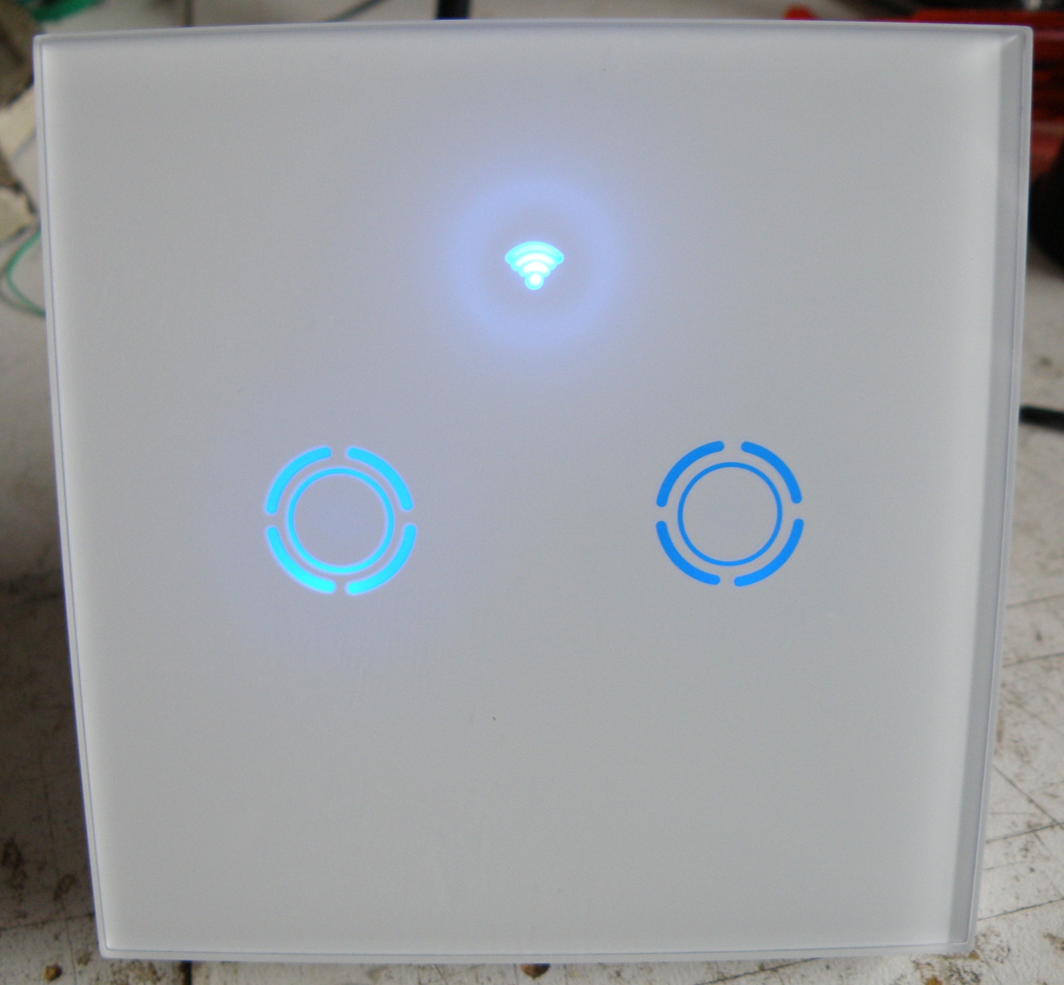
The EWelink touch switch is a similar product as the Sonoff touch, but I find the look a bit nicer. It’s more streamlined and is also available with black front.

The EWelink is sold in 1,2 and 3 gang version for the EU and US market.
I had only the 2 gang EU version, but it looks to me that the 1,2 and 3 gang EU version are the same. They left some parts out, but the pcb’s are all the same.
Can’t say anything about the US version, don’t have one to take apart.
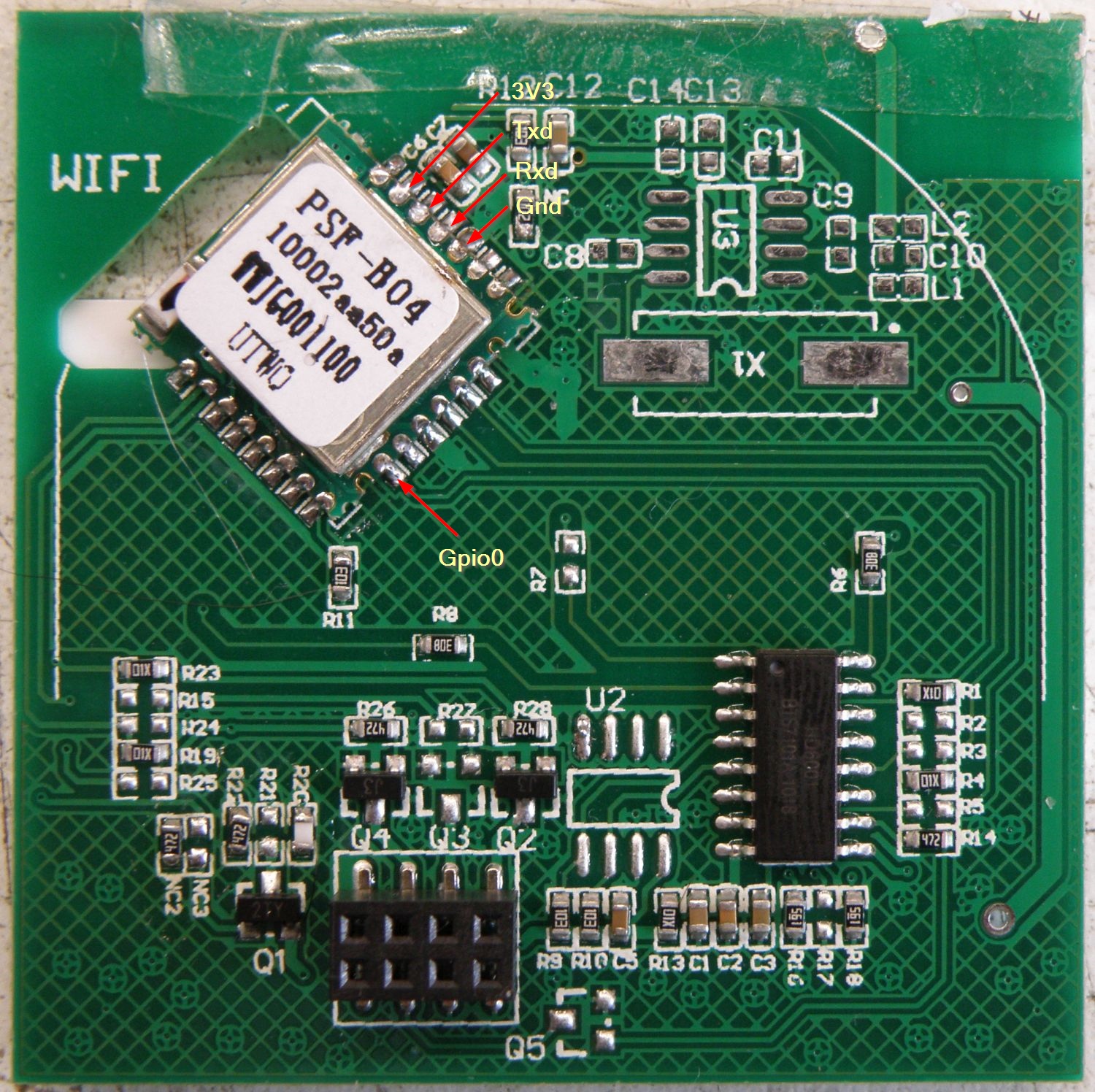
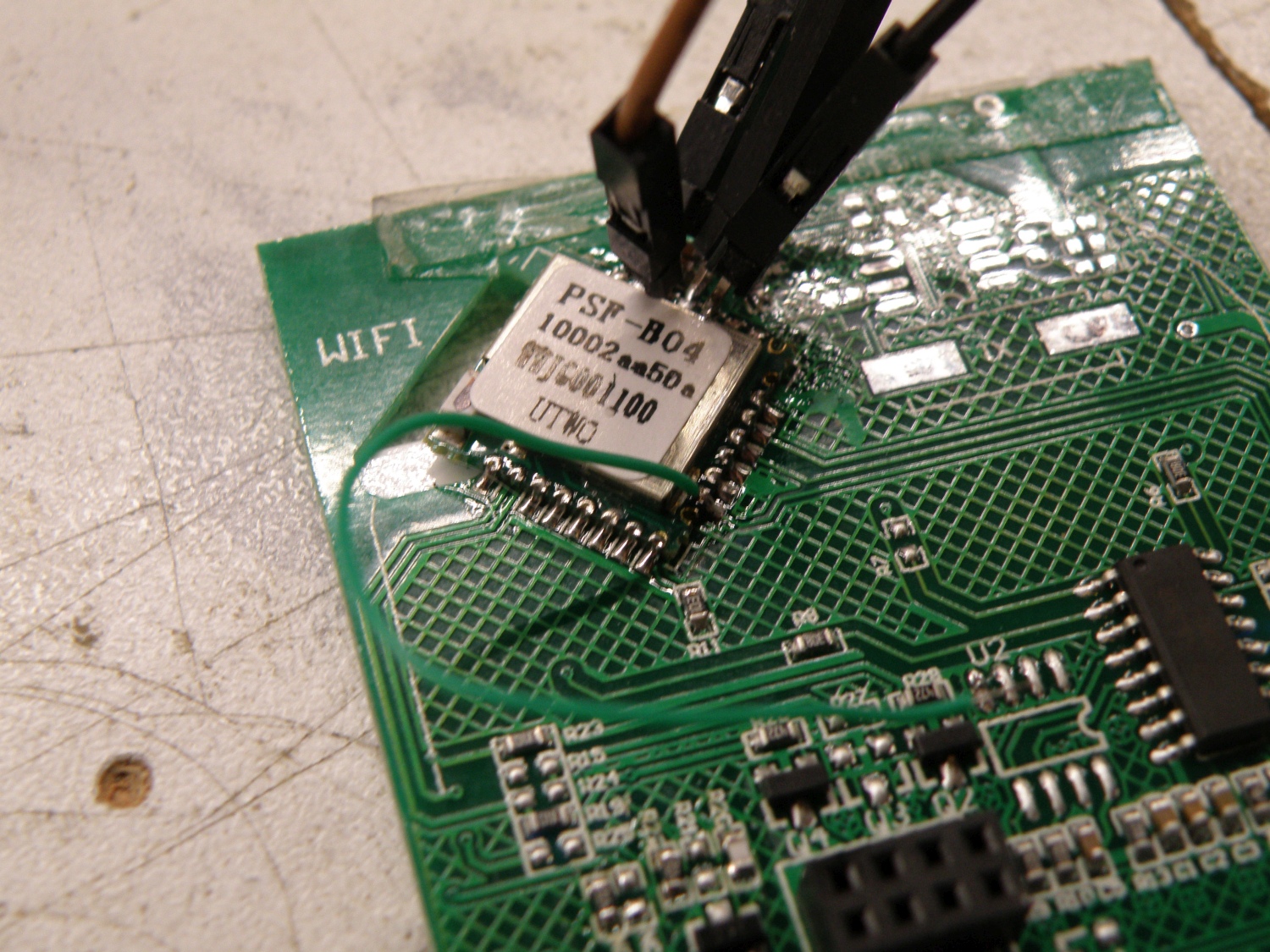
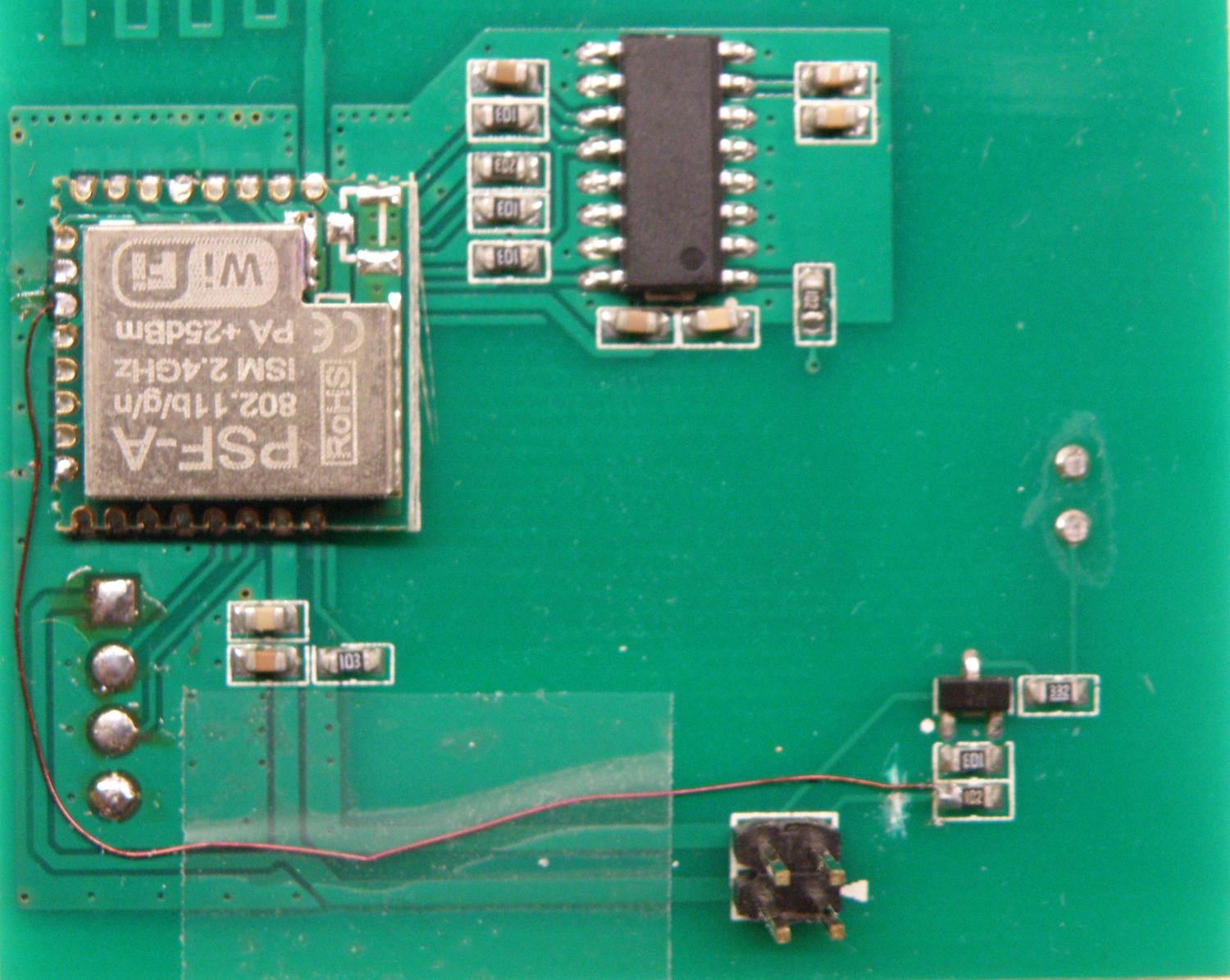
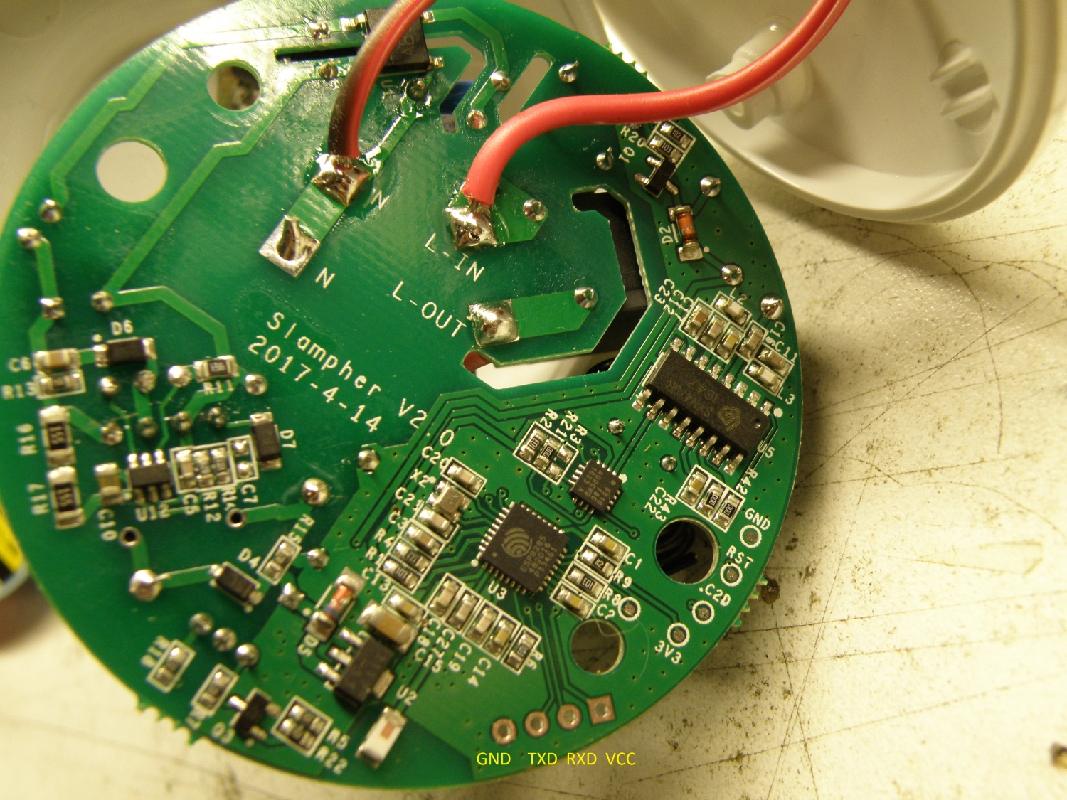
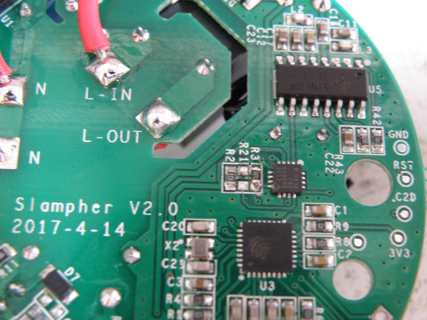
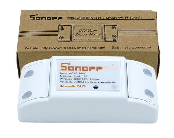
The hart of the EWelink touch switch is the PSF-B04 module. This module contains inside the well know ESP8285, that’s in fact an ESP8266 with build in 1M flash memory.

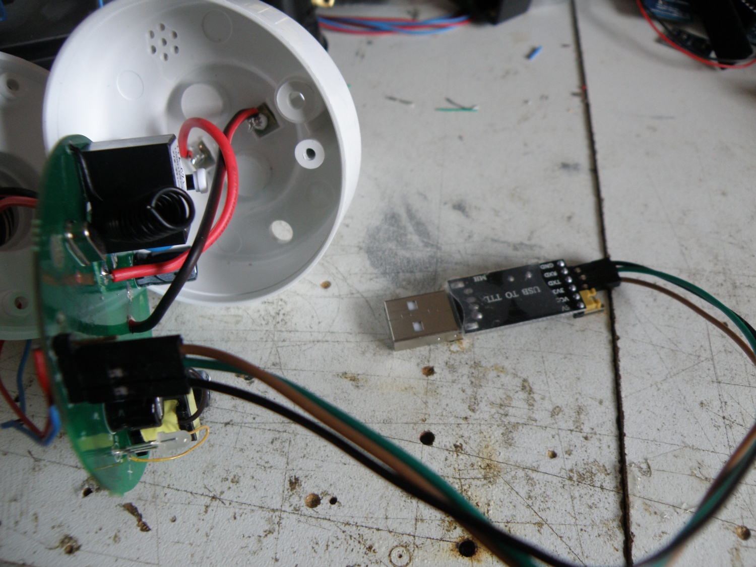
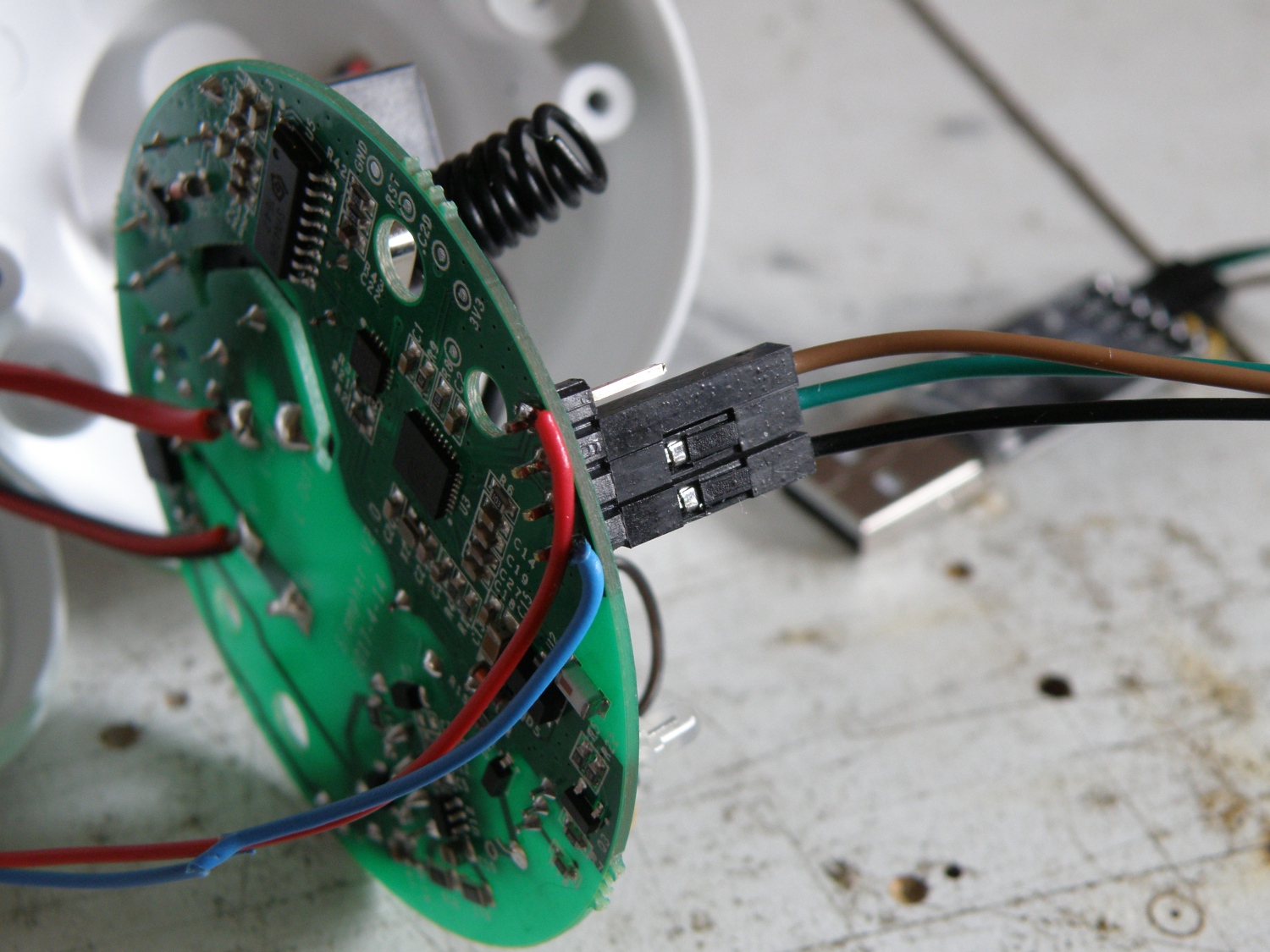
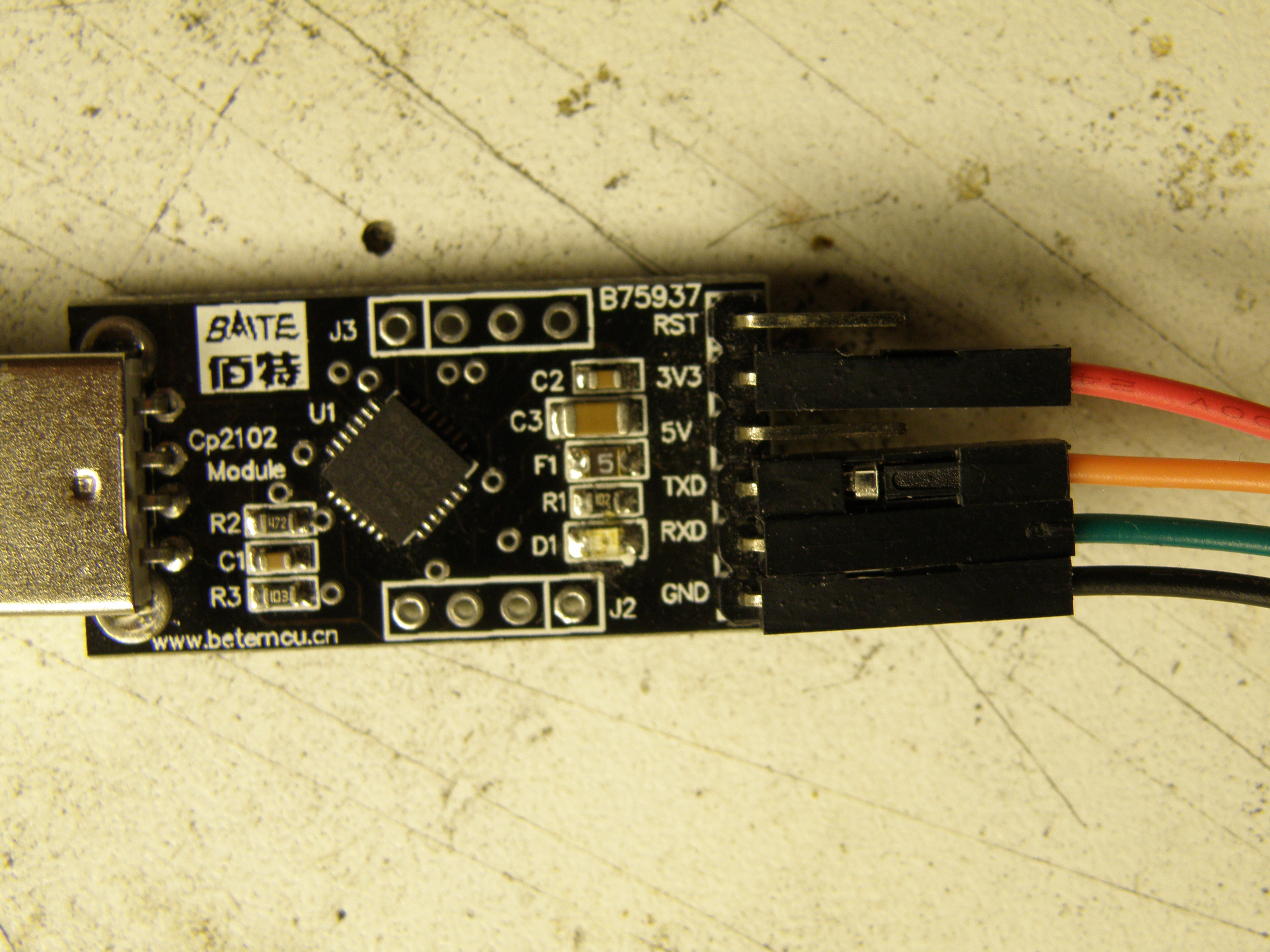
Just like the hacks for the Sonoff products we need to connect Txd, Rxd, Vcc, Gnd and Gpio0 to the touch switch to make it possible to upload our own firmware.
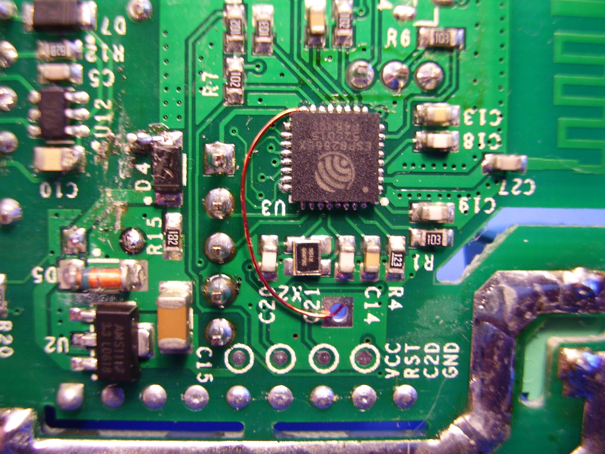
Bummer, EWelink didn’t provide us just like Sonoff with a header where most of the pins required are easy accessible.
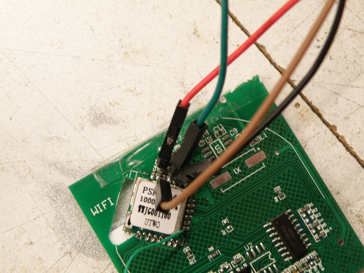
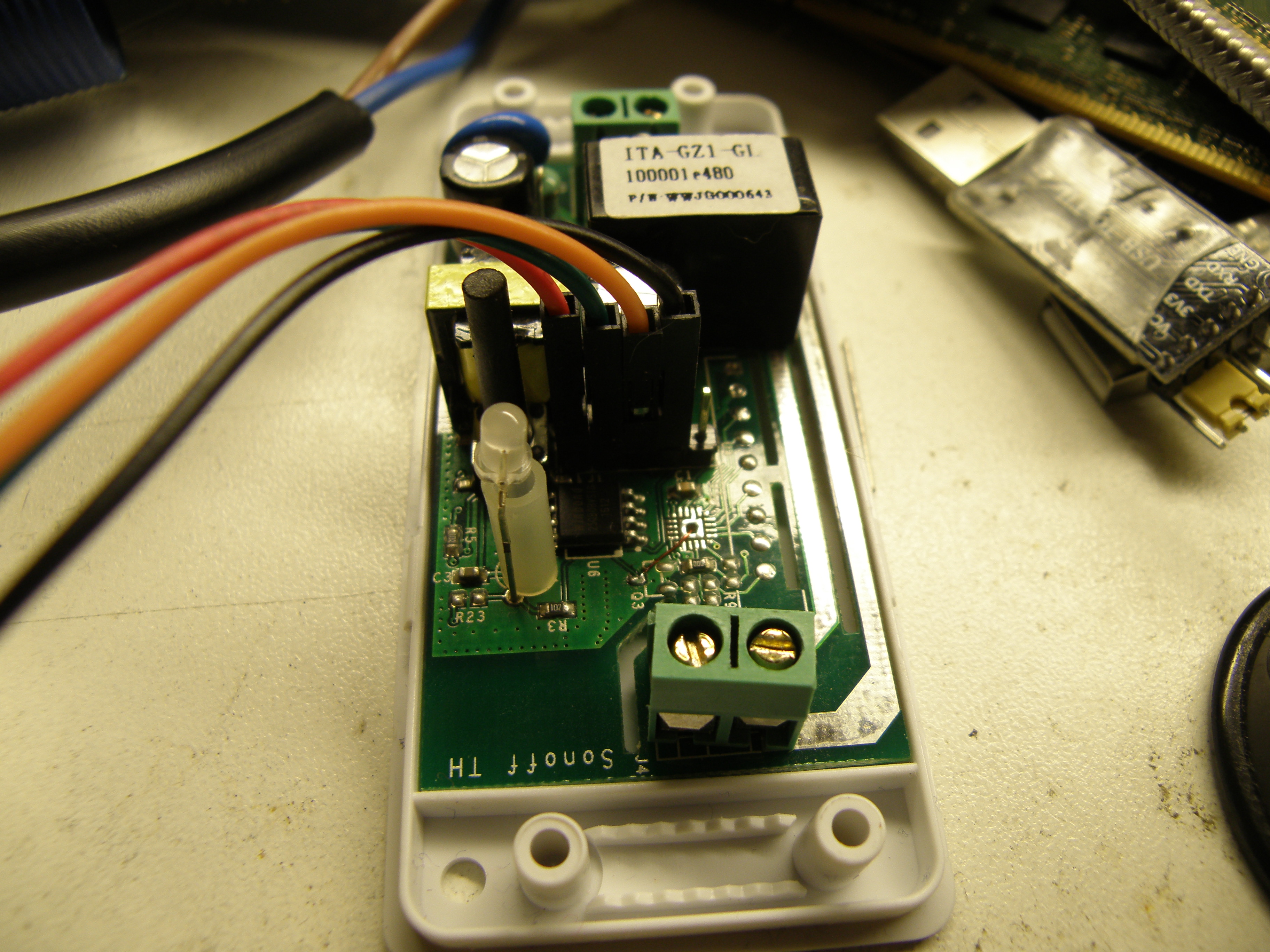
Time to get the soldering iron and solder some header pins direct to the PSF-B04 module. Because you can’t and won’t program the touch pcb when it’s connected to the power pcb, you need to provide it also with 3.3V power.
For the Gpio0 a simple wire will do the trick to get the ESP8285 in programming mode.

Pin mapping:

Wifi Led Gpio-13
Touch input Relay + led
left Gpio-0 Gpio-12
middle Gpio-10 Gpio-4
right Gpio-9 Gpio-5

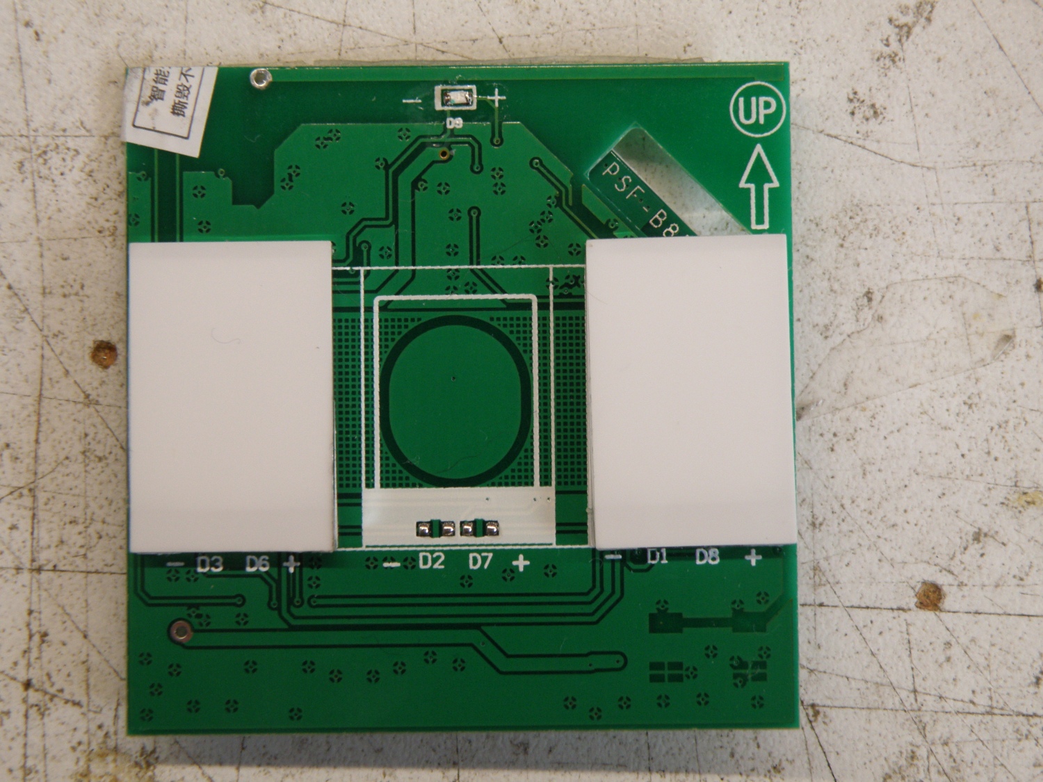
The 1 gang uses the middle touch sensor, the 2 gang uses the left and right touch sensor and the 3 gang uses them all.

Note:It looks to me now that they place some resistors in other places for the 1,2 and 3 gang. Think they do that for example so touch1 is always connected  to gpio0, but in the 1gang touch1 is in the middle and for the 2 gang the touch is at the left . Can’t verify this because I only have the 2 gang.

Arduino ide settings:
Generic Esp8285 Module
CPU Frequency: 80MHz
Flash Size: 1M (64K SPIFFS)
Upload Speed: 115200


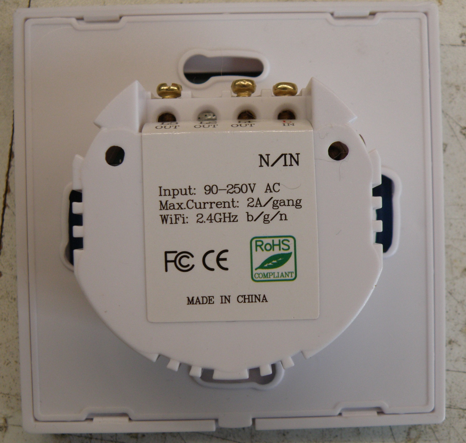
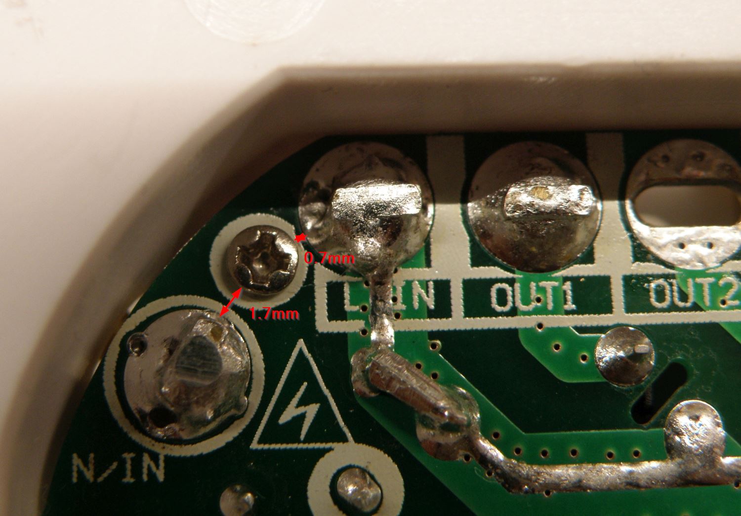
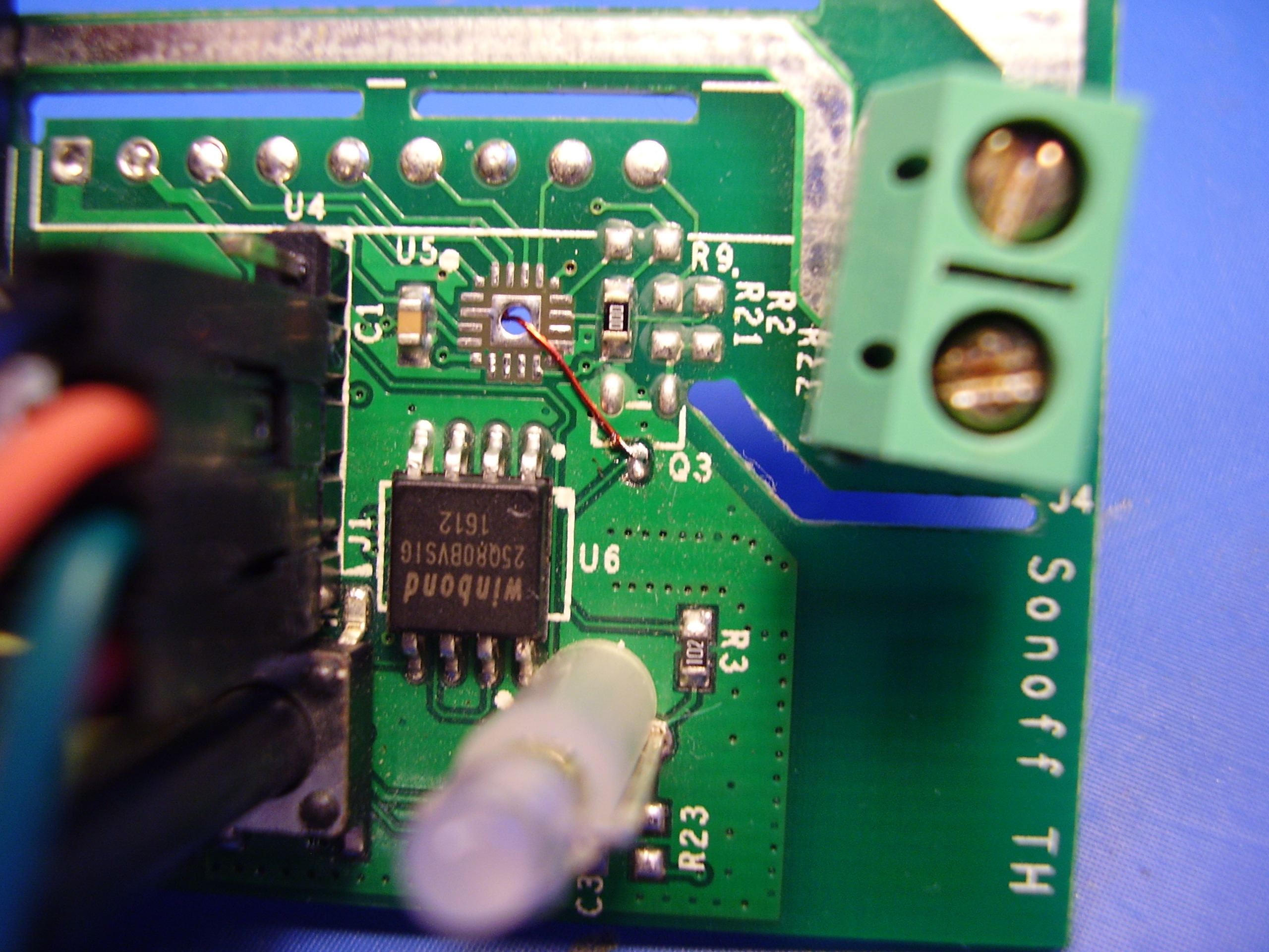
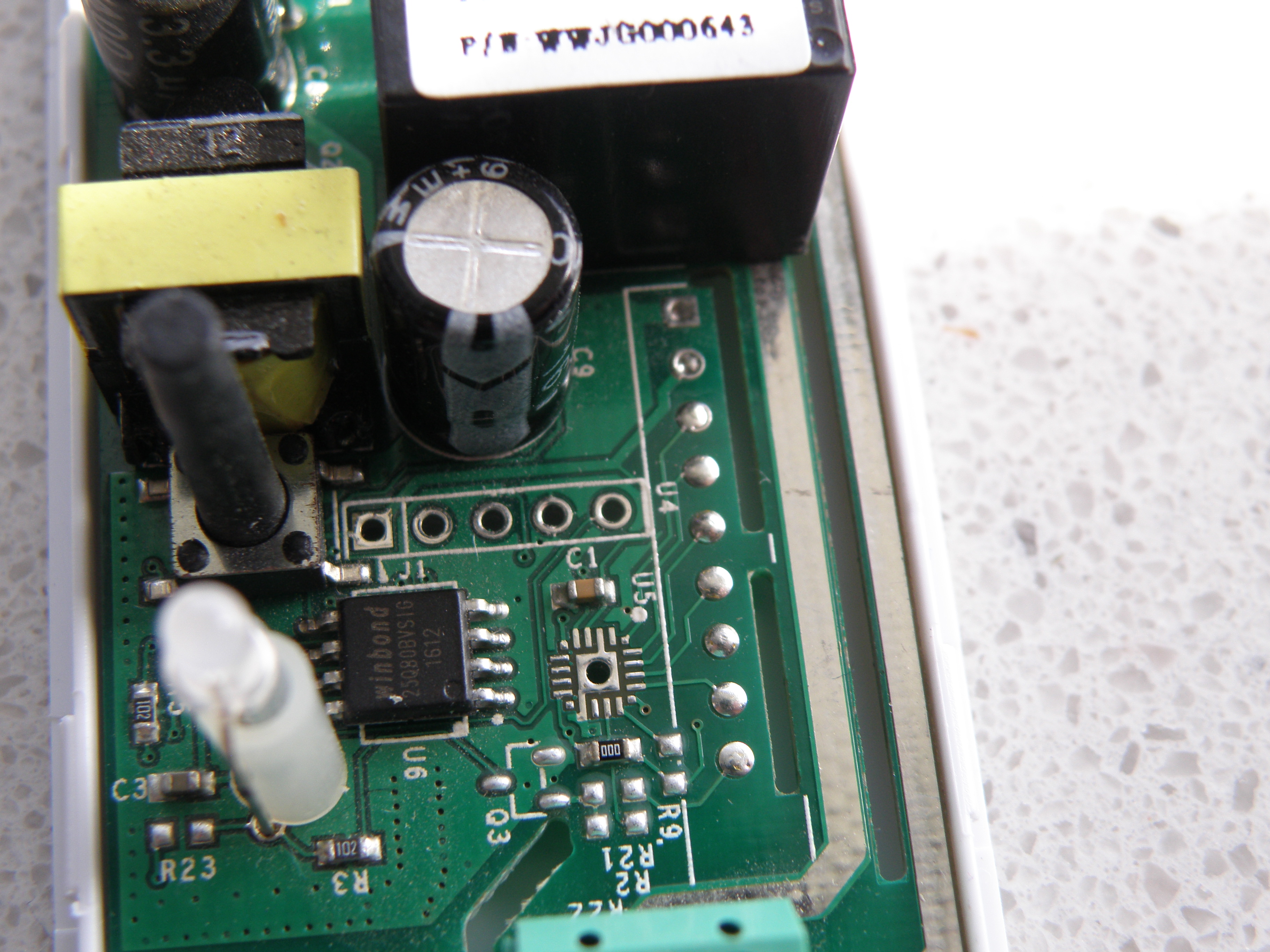
Important Note: As you can see in the last picture below they have placed a screw between the fase (L) and neutral (N) to hold the power pcb in place. The screw makes the isolation distance between the L and N to narrow. The minimum isolation distance requirement for 230V~ is 2.5mm and preferable  >3mm. With my Ewelink is was total 2.4mm, that’s not enough.
Simple solution, remove the screw, it doesn’t do anything. The power pcb can’t move because of the screw terminals and the other screws.
Do this all at your own risk.


Touch switch front
Touch switch back
Touch pcb
Pcb front connection
Programmer connected 1
Programmer connected 2
Isolation distance
PlayPause
previous arrow
next arrow
 
Touch switch front
Touch switch back
Touch pcb
Pcb front connection
Programmer connected 1
Programmer connected 2
Isolation distance
previous arrow
next arrow


Sonoff Touch Led Mod

Just like in all other Sonoff products one of the leds is hardwired to the relay and will lit up when the relay is switched on.
In my post over the Sonoff Wifi powerline switch mod I described how to put the led on a seperate IO pin of the Esp8266 so you can get full control over the led.
This post will do the same for the Sonoff touch led that’s behind the touch sensor.

The Sonoff touch has an Psf-a85 module on board from Itead, this module has the esp8285 inside. With the pinout and schematic available of the psf-a85 it’s easy to find the required pins.

You need to scratch the pcb track that’s going to the 1K resistor (see picture below). After that you need solder a thin wire between the 1K resistor and one of the free IO pins on the psf-a module, in the picture I choose pin 3 IO4.

Now you have full control over both (wifi and touch) led.
My idea was to let the touch led glow so you can find the touch button easy in the dark.

If you don’t know how to flash the esp8285 have a look at this.
Personally I add to all my ESPxx programs the OTA (over the air) flash capability’s so you can remove the usb to serial convertor and close up the housing for safety purpose and flash new firmware ota.

Arduino ide settings:
Generic Esp8285 Module
CPU Frequency: 80MHz
Flash Size: 1M (64K SPIFFS)
Upload Speed: 115200

Demo/test Sketch at Github


Sonoff Touch, Touch led glow


Sonoff Slampher V2.0

The Sonoff Slampher is a very interesting product for you domotica project if you don’t want to be to invasive in your electric system.
Factory default the Slampher has some descent software with a nice app, but if you want more for example connect is to your Mqtt broker you need to change the firmware.
If you want to program your own software or other software the can be found on the internet then you have to reprogram the ESP8285 inside

There are enough tutorials on the net how to reprogram the Slampher, however the Slampher that I bought on Ali Express is a new V2.0.
This version has an ESP8285 on board in staid of the famous ESP8266. The ESP8285 is ruffly the same as the ESP8266 except that it has an build in 1MByte flash memory.
With the Arduino ide the ESP8285 can also be programmed, luckily

Lets start;
To get the ESP8285 in flash mode we need to connect GPIO0 to the ground. To connect the button on the Slampher to GPIO0 we need to move a resistor. Normally the button is connect to the RF part to learn the Slampher the rf remote. We want to program the ESP8285 and for that move R21 to R3. It’s an 0Ω resistor so a piece of wire or solder will also do the job.
After that you need to connect your usb to serial convertor.  Pin 1: Vcc, 2:rxd, 3:txd and 4:gnd . The ESPxx works on 3V3 so don’t fry it with the 5V output of your convertor.
My convertor didn’t have enough mA to supply the Slampher direct so that’s why you see on the pictures a separate 3V3 power supply.
Press the button and insert the usb convertor in your computer and happy flashing.
Don’t connect the Slampher to the mains for your safety.
Personally I add to all my ESPxx programs the OTA (over the air) flash capability’s so you can remove the usb to serial convertor and close up the housing for safety purpose and flash new firmware ota.
The relay won’t work if you not connect the Slampher to the mains, it needs the 5V from the transformer.
Here is a small sample on GitHub to get is working, button, relay, ledgreen are supported. Ledred and the rf receiver are not (yet) supported.

Arduino ide settings:
Gerneric Esp8285 Module
CPU Frequency: 80MHz
Flash Size: 1M (64K SPIFFS)
Upload Speed: 115200

Overview pcb
Usb to serial
Powersupply
Move R2 to R3
PlayPause
previous arrow
next arrow
 
Overview pcb
Usb to serial
Powersupply
Move R2 to R3
previous arrow
next arrow
Sonoff Wifi powerline switch mod

Found this interesting Wifi power switch on Ebay for only $6,11.  It’s not clear to me if this is the original design or a copy of it. Detailed info can be found on this Wiki page.

Sonoff TH powerline switch

To connect it to my Mqtt broker and domotica I wanted to make my own firmware.
Easy said, easy done. There are plenty example on the net how to do this. Because there’s an esp8266 inside there are also numerous Arduino software example available.
First step was soldering a header to the empty programming socket and connect my Usb to serial adapter to it. Take a note that you must have a 3.3V usb to serial adapter, they can be found for under a dollar on ebay. Don’t know how they can make it for that amount and even send it to the other side of the world.
Connected the usb adpater to my pc and voila, I’m in. Keep also in mind not connect it to the mains when connected to your pc. Both powersupply’s are not happy with each other.
Simple led blink program was working, connecting to wifi was also working, but unfortunately the red led and ota (over the air) update was not working.
The ota was complaining that the authentication was not correct and I was sure it was correct.
After lot of Googleing and some tries it was clear that the memory settings in the Arduino ide where not correct, but what must it be then?
This setup was working for me, cant say it will work for all Sonoff versions, but you can try setting the ide like this.
/*
    Gerneric Esp8266 Module: Flash Mode: DIO, Flash Frequency: 40MHz, CPU Frequency: 80MHz
    Flash Size: 1M (64K SPIFFS), Debug Port: Disabled, Debug Level: None,  Reset Method: ck
 */

Now the red led.
In some Arduino code that I found they say that the red led will lit when the relay will be activated. But both didn’t work. Red led and relay didn’t worked. Relay was simply fixed, it needed the 5V from the Sonoff build in power supply, connected to the mains and the relay worked, but still no red led.
Looking at the schematic and the pcb some critical components for the led where not placed. Q3, Q4, R2 and R23 are not placed.
Q3 and R2/22 are used for the Sonoff version that have also the 433Mhz receiver. Q4 and R23 are used to lit the red led if the relay is activated.
Both are not placed, so that’s why the led will not lit. If you want to let the red led work together with the relay, just place Q4 (2N7002) and R23 (1K) and it works.
However I wanted the red led under software control and decided to use one of the free gpio ports from the Esp8266.
Soldered a wire from gpio4 (pin16) on the Esp8266 to the drain of Q3. See the pictures below for details.

That’s it everything working as wanted.

Wire connected to IO
Wire other side connected to Q3
Programmer connection
Usb 2 serial connection
Programmer connected to Sonoff
PlayPause
previous arrow
next arrow
 
Wire connected to IO
Wire other side connected to Q3
Programmer connection
Usb 2 serial connection
Programmer connected to Sonoff
previous arrow
next arrow