EvertDekker.com

Evert Dekker
  • Home

Search

Recent Posts

  • Raspberry Pi Power distribution board
  • Doublelock Sensor
  • Nixie Clock #3
  • Iot house exhaust air systems controller
  • PZEM-016 Energy Monitor

Projects

  • expandCode Vault (14)
    • expandArm Cortex (1)
    • expandBascom (10)
    • expandMini2440 (1)
    • expandVB 5..2010 (2)
  • collapseElectronic Projects (66)
    • expandEsp32 (4)
    • expandEsp8266 (13)
    • expandJoshua Domotica (25)
    • expandOldies (3)
    • expandRc Car Projects (4)
    • expandVarious Projects (17)
  • expandSoftware (9)
    • expandArduino (1)
    • expandJoshua (1)
    • expandNokia N900 (1)
    • expandPC (6)
  • expandVarious projects (3)

Popular Posts

  • Iot SensorV2 with battery onboard
  • Contact me
  • Raspberry Pi Power distribution board
  • Raspberry Hat board template Altium
  • PZEM-016 Energy Monitor

Archives

Menu

  • My Tube
  • Contact me
  • Privacy Policy

Counters

  • 1236097Total reads:
  • 99Reads today:
  • 226Reads yesterday:
  • 2157Reads last week:
  • 5165Reads per month:
  • 403550Total visitors:
  • 50Visitors today:
  • 120Visitors yesterday:
  • 1242Visitors last week:
  • 2780Visitors per month:
  • 170Visitors per day:
  • 0Visitors currently online:
  • September 9, 2007Counter starts on:

My Github Projects

  • Blinkled
  • DHT22-Esp8266-HW-Test
  • DHT22-ESP8266-Temperature-Node
  • ESP8285-Sonoff-Slampher-V2
  • IotPirLight

Meta

  • Log in
  • Entries feed
  • Comments feed
  • WordPress.org

Iot light switch with mains input

Jul14
by Evert on July 14, 2018
Posted In: Esp8266

IOT light switch with input for switch with mains.

The idea is the same as the famous Sonoff wifi switch but this one has also an input for a 230V~ switch so you can still use your existing light switches.
Most of the light in my house is replaced with Sonoff touch switch , however this is not possible everywhere. For example on the stair case we have what’s called a switching circuit (wisselschakelaar for the dutch readers) and due to the wiring it was not possible to replace them both with a Sonoff touch switch.

To detect the present of the mains on the input I started with a simple schematic based around the H11AA1 which you can find a lot on the net as mains or zero cross detector for Arduino. This worked flawless, see the photo of my experiment. With the CTR (current transfer ratio) of 20% it was necessary to have a current of at least 3.3mA through the led of the opto-coupler. With the used current limiter resistors of 2x33K this will dissipate 0.71W.
Not that much energy to “waste”, however depending on the state of the switching circuit and the Mqtt state this “wasting” can occur 24 hours a day, this can be done better.
Searching for an opto-coupler with a higher CTR should do the trick. The SFH6286-3 has a CTR of 100~320%, a led current of 1mA would be enough with this CTR ratio.  2x110K Resistor will limit the current to 1mA and will dissipate 0.22W.
That’s 0.5W less then before, that will save 4.36kWh per year maximum.

Note: All calculation done in this post where done for 230V~ 50Hz.

The rest of the circuit is not that special. The Esp-01 is programmed with an external programmer and then equiped with a OTA bootloader so programming is only needed to be done once (theoretically). To have enough room for the OTA bootloader and the sketch I have updated the memory from the esp-01 from 1MB to 4MB. That’s easy done with a hot air gun to replace the memory chip. 4Mb spi flash chips can be bought very cheap on ebay.
The solid state relay will consume 6mA at 3.3V, this is broad within the max pin GPIO current of the ESP8266 so no transistor driver is needed.

Because the Esp-01 doesn’t have that much IO pins available the RX and TX can also made be available as IO, to disconnect them from the uart use:

pinMode(1, FUNCTION_3); //GPIO 1 (TX) swap the pin to a GPIO.
pinMode(3, FUNCTION_3); //GPIO 3 (RX) swap the pin to a GPIO.

You can still use the TX/RX pin to program the ESP-01, but using them in your sketch is not possible anymore. To still have the possibility to debug I use a remote debug library to debug over telnet.

Schematic Schematic
Dangerous experiment Dangerous experiment
Output from the optocoupler Output from the optocoupler
Output from the optocoupler with capacitor Output from the optocoupler with capacitor

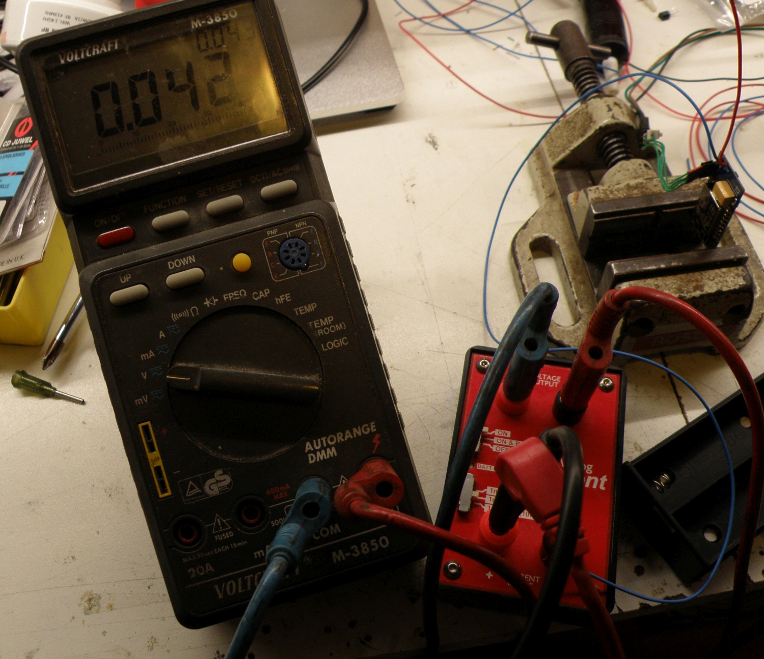
Current trough the opto coupler led Current trough the opto coupler led
Bare pcb Bare pcb
Pcb Finished Pcb Finished
Test Setup Test Setup

Buildin light fixture Buildin light fixture


If you want to make your own, or use parts of the design here are  the Altium Designer 16 files:

Download Now!
1089 Downloads

 Comment 

Esp-01 Programmer Mod

May24
by Evert on May 24, 2018
Posted In: Esp8266

For a small project of my there was needed a programmer for the Esp-01 wifi module to program the module. It’s not really a programmer, but more an usb to serial convertor.
Simple search on Aliexpress gave a nice looking programmer that you can stick in your pc and voila Esp-01 can be programmed, can be bought for $0.78 including shipping.

Bummer, when it arrived and want to use it to program the Esp-01 module it wasn’t possible to get it working with the Arduino ide. The ide was constant coming with the error espcomm sync failed and other com port related errors.
After a quick google search it was clear, the bought Esp-01 programmer works fine out of the box when you use the Esp-01 with the AT commands, but for using it with the Arduino Ide the Esp-01 module had to be set first in programming mode by connection GPIO-0 to ground and reset the module to bring it in flash uart download mode.
Most of the solutions found on the net uses 1 or 2 buttons to get this accomplished, but I wanted automatic programming mode just like the NodeMCU does. Just press upload in the Arduino ide and go….

The programmer uses the same usb to serial convertor (CH340G) as used in the NodeMCU so it should be possible to use the same schematic. The Arduino Ide already supports the NodeMCU so no need to change drivers, board.txt or platform.txt files.
The part that’s responsible for pulling GPIO-0 low and resetting the Esp-8266 is only two general purpose npn transitors and 2 resistors.

Schematic

So I added 2x BC547 (or use any other general purpose transistor) and 12K resistors to the bottom of the programmer board. It’s not my best soldering work, but it will do the job.

Bottom View

Soldered 2 wires to pin 13 and 14 of the CH340G and connected them to the transistors on the other side.
You can fix everything with some hotglue if you want.

Top view

Change in the Arduino ide the setting Tools , Reset Methode to NodeMCU and you are ready to go.
Every time you press now upload the Esp-01 will be set in serial download mode and you can upload you fresh developed code.

Arduino Ide Setting


Happy programming.


1 Comment

Iot SensorV2 with battery onboard

May05
by Evert on May 5, 2018
Posted In: Esp8266

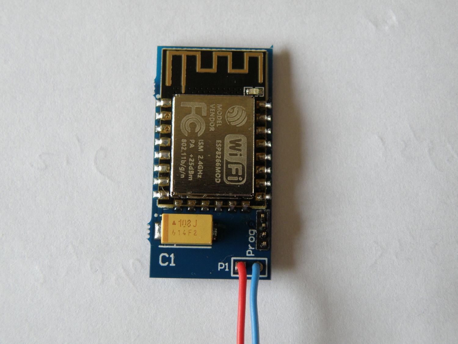
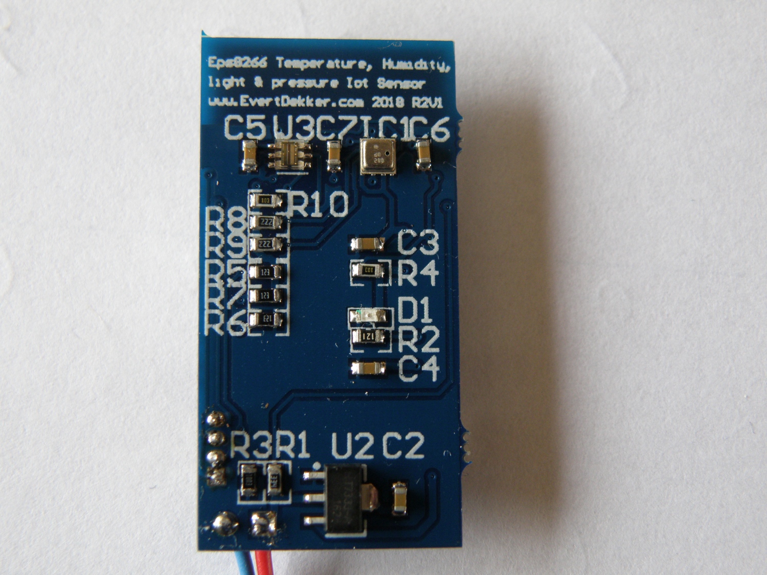
Not a complete new design, but a redesign of my Iot Esp8266 sensor V2, the schematic is exact the same however this time with a on board 18650 3.7V Li-ion battery.

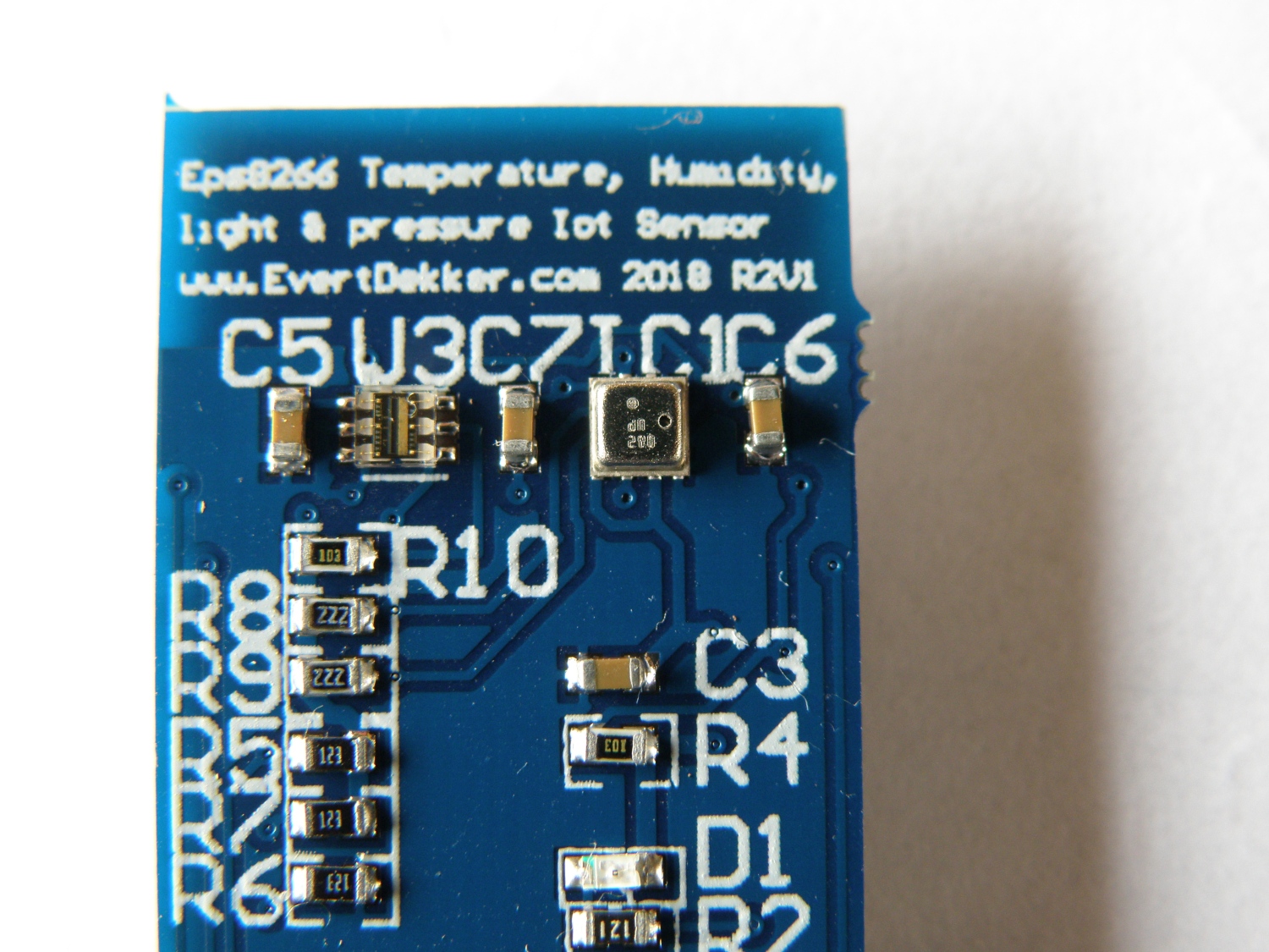
The Iot sensor node will measure temperature, humidity, atmospheric pressure and light. The light is measured with the TSL2561 and temperature, humidity, atmospheric pressure with the Bosch BME280.

In the previous design the battery was placed in a separate battery holder and the pcb was taped to the battery, not really the ideal solution.  So the idea was born to combine everything on 1 pcb.
The first idea was to place the battery beside the electronics, when this was finished I thought that can be smaller and made also a design where the pcb is on top of the battery. Still I couldn’t decide if I wanted the side or top version. Ok, lets combine both designs and we will see later what’s version is nicer.
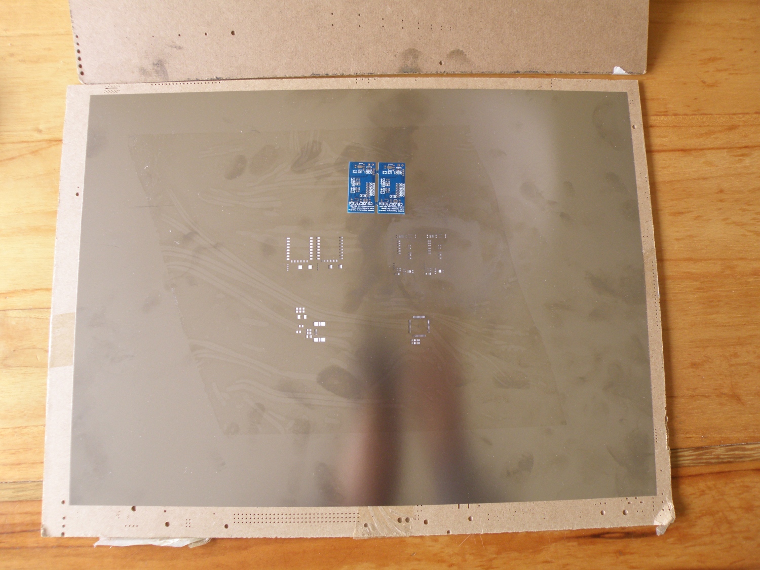
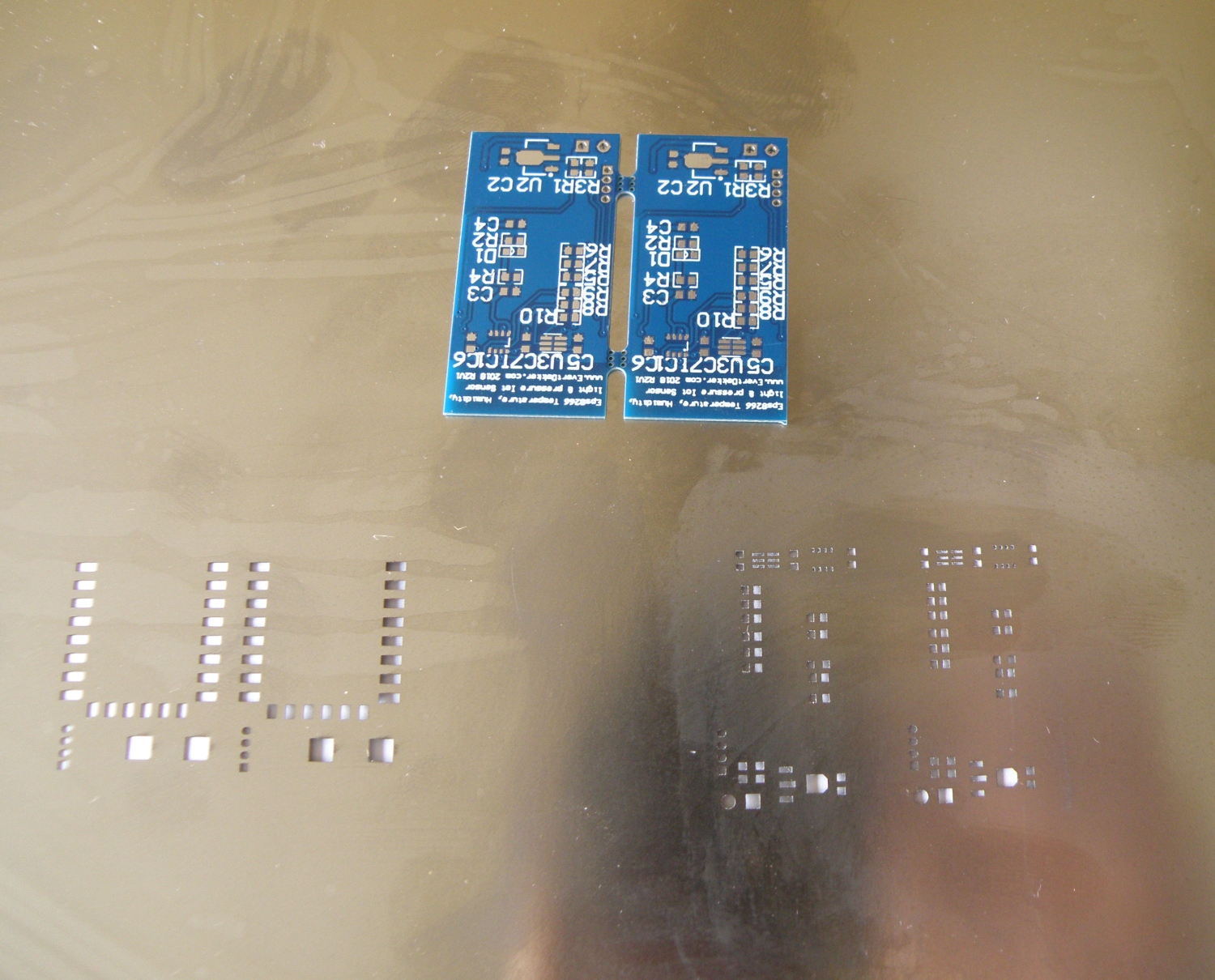
Just as mentioned in then previous design, it’s very hard to solder the BM280. My opinion is that you only can solder it good if you use a stencil to apply the solder paste and place the pcb in the oven or use a hot air station.
For the battery clips I used the Keystone 16~19mm PC Battery clip.  In the datasheet they note that for an 18650 with build in protection circuit you need 48mm between the front solder pins, that will make it fit for battery’s of 68mm if you add the rest of the clip. However I don’t think this is correct, at least not in my case. 18650 battery with build in protection are 69,7 mm long, it will fit but it looks that it’s way to tight. For 18650 battery with flat head the clips are to far apart and won’t make contact. An 18650 with button head will fit perfect. If you want to make your own sensor node, keep in mind that there are a lot of different sizes 18650.
I’m using now the Sanyo NCR18650GA 3350mAh – 10A Button Top and that fits perfect, they are 66.7mm long (battery used on the photo’s is not the Sanyo).

Always nice to preview the design in Altium Always nice to preview the design in Altium
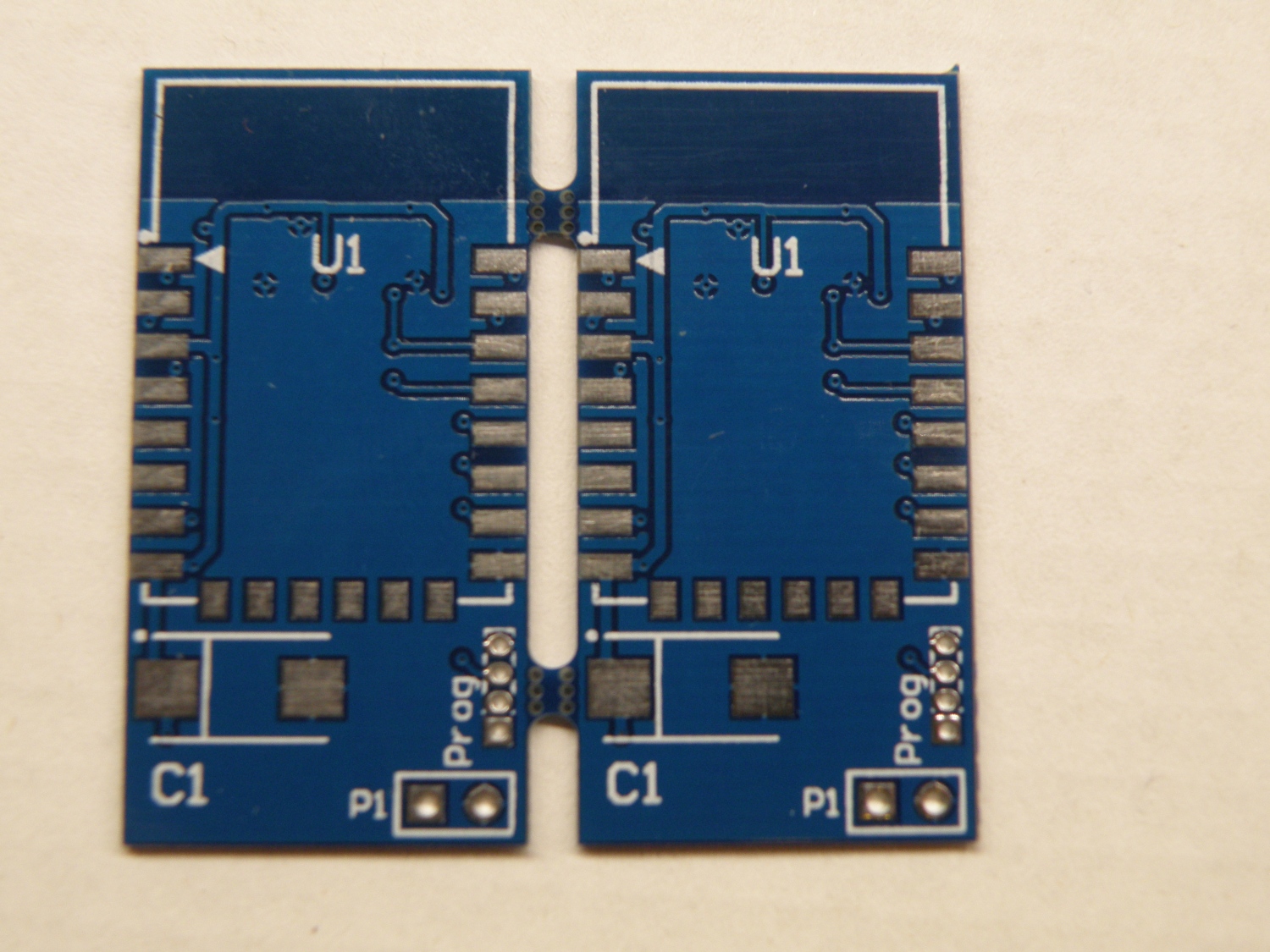
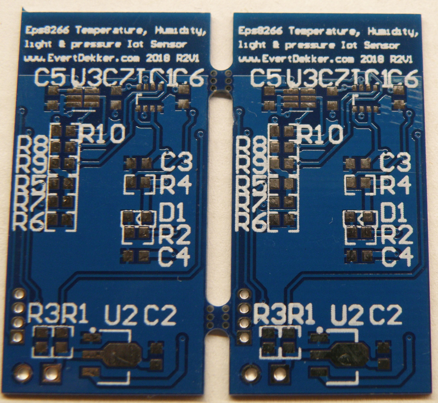
Pcb and stencil Pcb and stencil
All the components are placed All the components are placed
The version that sits on top of the battery The version that sits on top of the battery

Pcb slightly bend with this battery Pcb slightly bend with this battery
Battery next to electronics Battery next to electronics


You can find a test/demo Arduino program on my Github.


If you want to make your own, or use parts of the design here are  the Altium Designer 16 files:

Download Now!
1107 Downloads


  • Page 4 of 30
  • « First
  • «
  • 2
  • 3
  • 4
  • 5
  • 6
  • »
  • Last »

©2007-2021 Evert Dekker 2015 | Powered by WordPress with Easel | Subscribe: RSS | Back to Top ↑