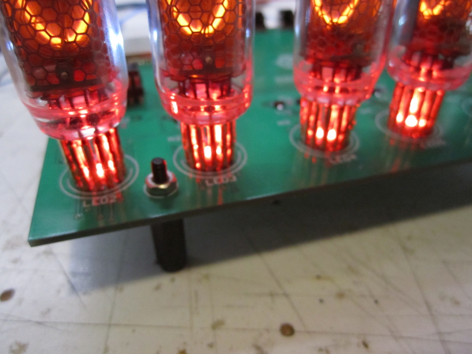
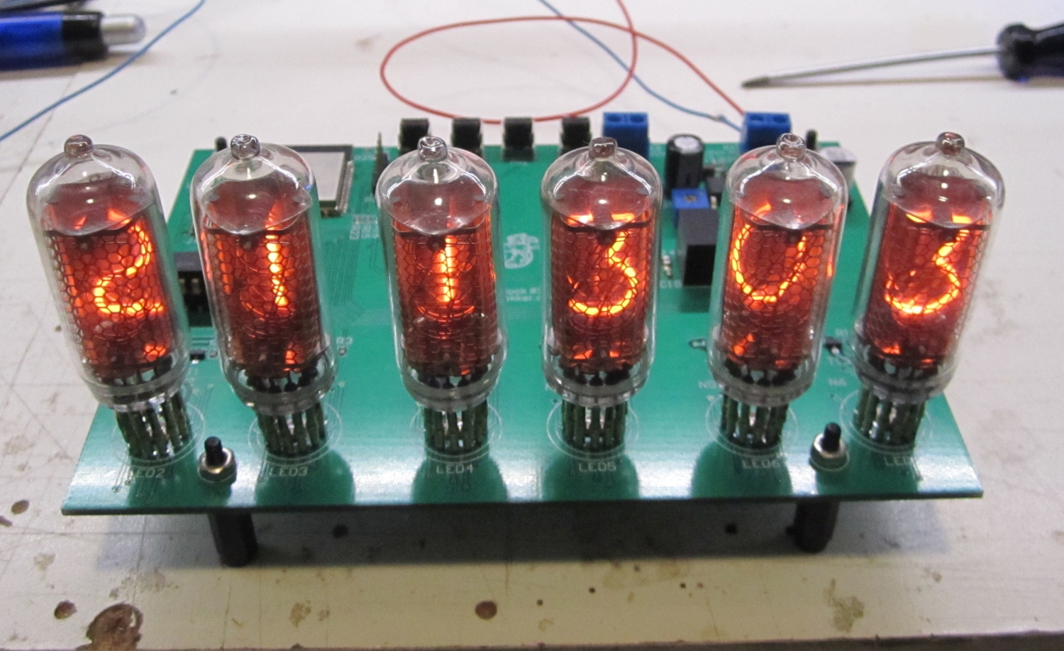
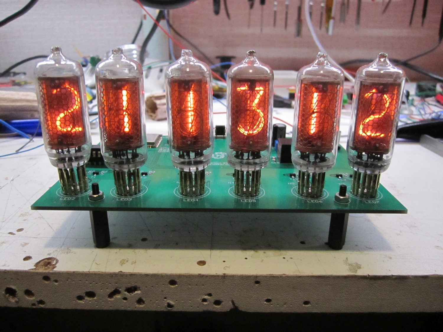
I still had laying around some IN-8 tubes that I bought a couple of years ago by mistake. The plan was to order IN8-2 tubes as spare for my Nixie #1 clock, but for some reason I didn’t read the specs good enough from the e-bay seller.
Nixie clock #1 did get his time update over the Joshua domotica network from the Tcp/ip gateway. This works perfect, however for the new design a stand alone time update would be nice, so no gateway but direct over wifi to a ntp server.
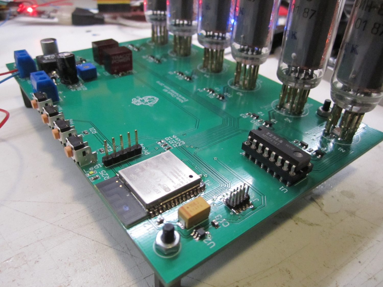
To accomplish this I was thinking about an Esp82666 or Esp32. The Esp8266 in the form of an Esp12 didn’t had enough gpio pins, so the Esp32 was the winner.
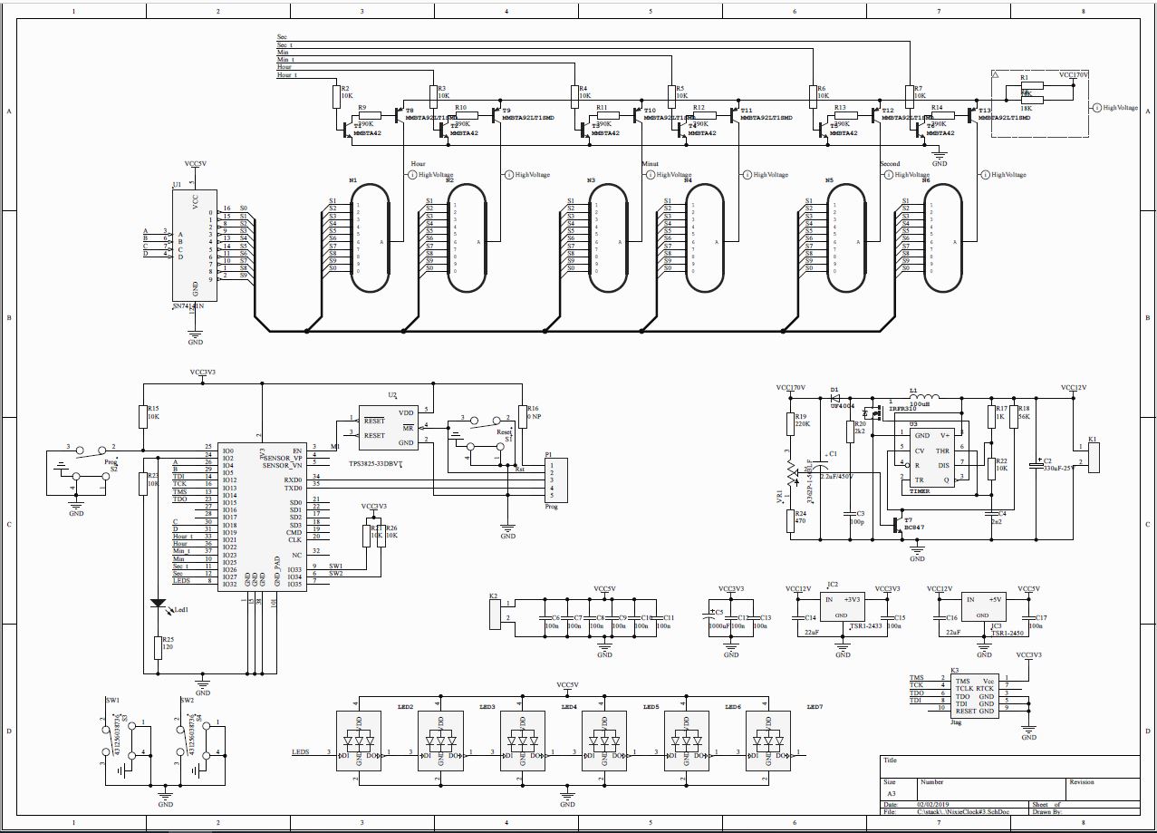
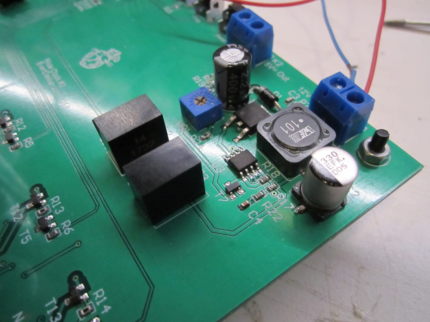
Major parts of the schematic is recycled from my first 2 nixie clocks. High voltage power supply, multiplexer and anode drivers are kept the same. The foot led lighting (I know some of you guys hate it) are this time rgb and to save some IO pins they are from the daisy chain type, the SK6812 in 3.5×3.5mm package. These leds requires 5V and the Esp32 requires 3.3V, so for these voltages I used ready made Tracopower switching step down regulators.
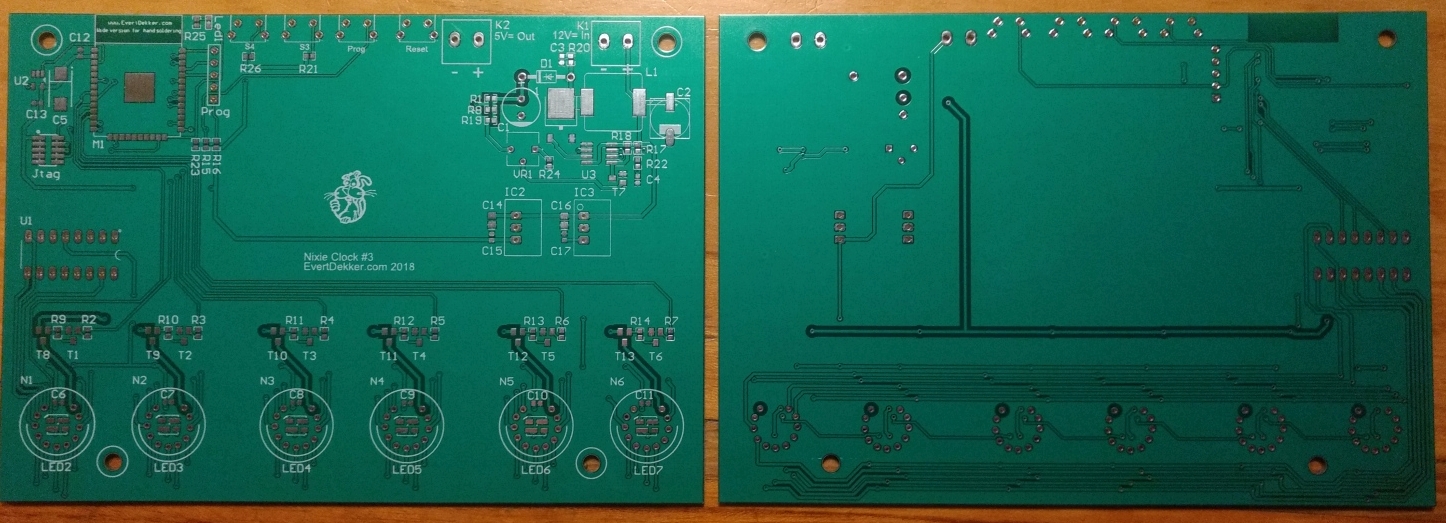
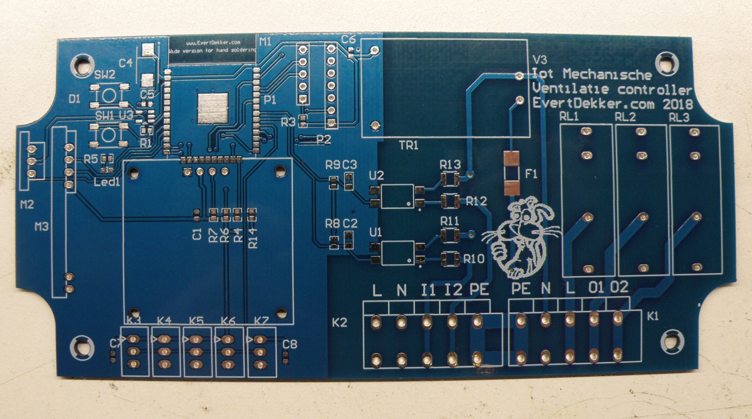
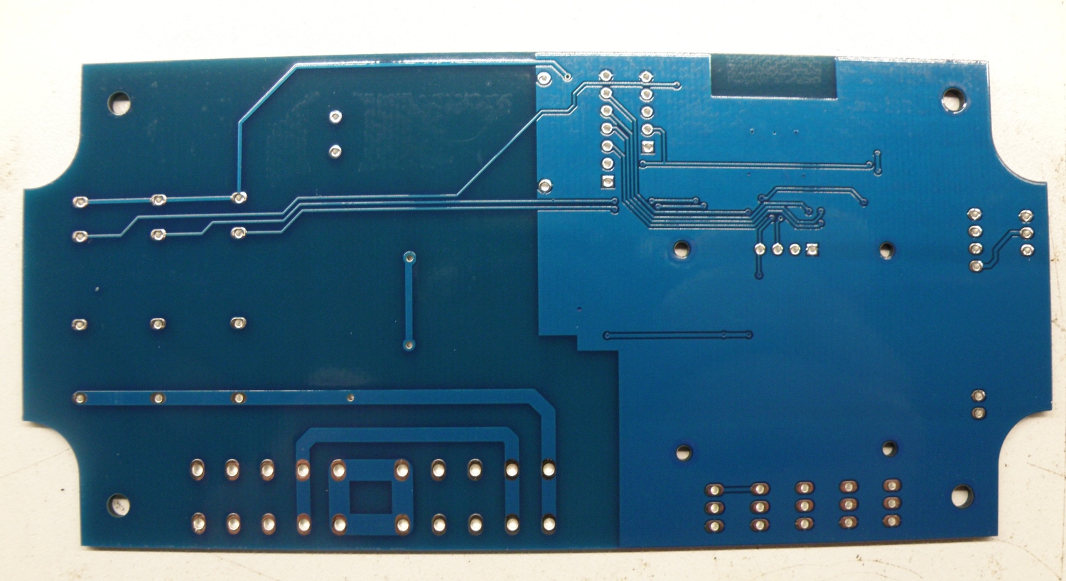
Pcb was designed in Altium and made by Elecrow. The design of the pcb is so that it will fit in the (old) enclosure of my Nixie clock #1, that’s why the pcb is for the biggest part empty.
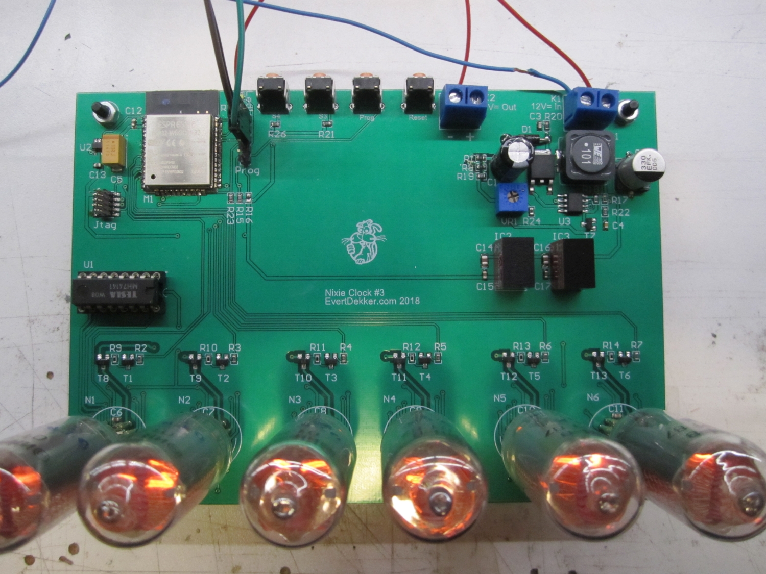
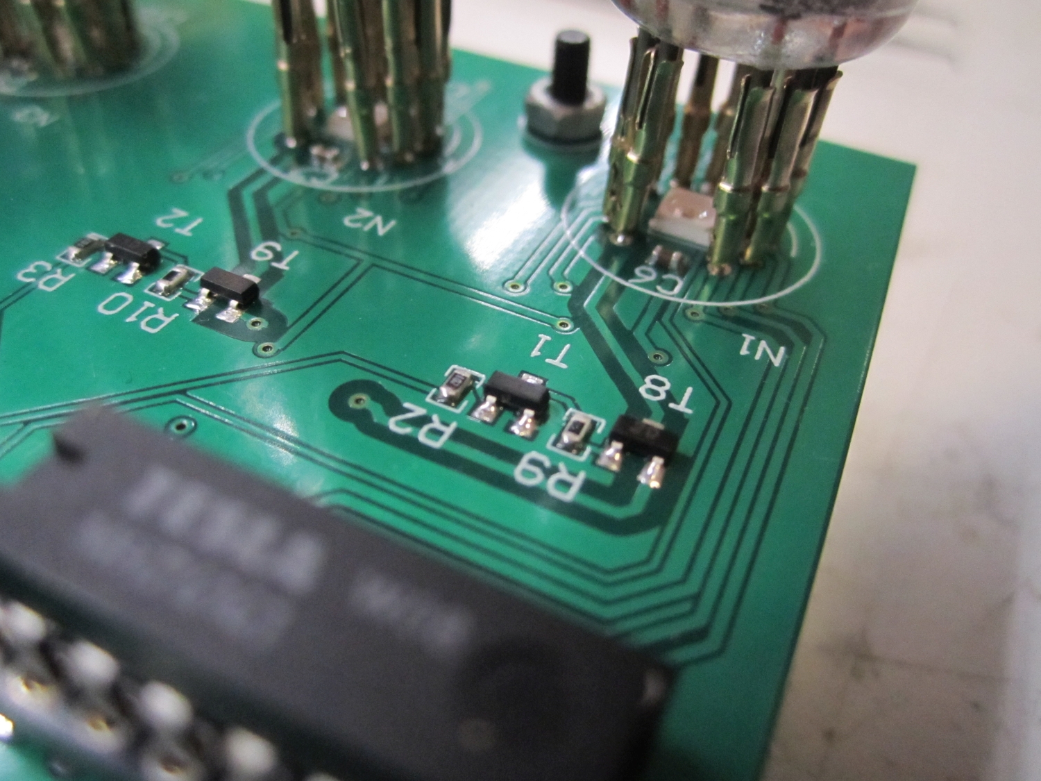
Assembling the board was not that hard except for the SK6812 leds. Due the poor mechanical structure of the chip is hard to solder them. Hand soldering is not possible, even with the heat gun it was difficult because the melting point of the plastic was close to the melting point of the solder. I managed to get it done by applying solder paste to the pcb, preheated the board from the bottom with a pre-heater and finished the soldering with the heat gun. Working fast was a must, but due the preheating the time that the air gun needed to be hold on the led was very short.
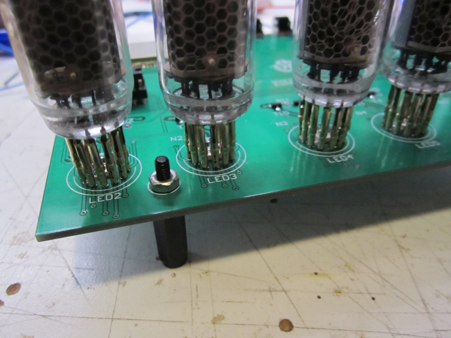
The nixietubes are mounted in socket for easy replacement and mounting.
The software was written with the help of the Arduino ide and Esp32 core. Because the ESP32 doesn’t have a PORT like the Atmel cpu’s is harder to control the rows and columns. Normally you send the digit to the port and with the help of a mask the BCD to decimal decoder it’s easy to set pins from a port according the values for the digit. For the Esp32 it was necessary to control every pin individuality with DigitalWrite, have a look at code to see want I meant and how it’s done.
Multiplexing the tubes is better for the lifetime and easier for the power supply etc. Multiplexing the tubes with an interval of 2ms gave the best result, you don’t see the tubes flickering and they still give enough light. The Esp32 runs on FreeRtos the idea was to use a separate task for multiplexing and updating the tubes. It looked that this was working fine wasn’t it that it looks that sometime one of the tubes gave some more light. Measuring with the scope on the base of on of the drivers confirmed me that sometimes the interval wasn’t 2ms but 3ms. I tried almost everything, high priority, more stack etc. but the problem stays.
Time to go back to the drawing board and start over with the multiplex part of the code. This time I have used a hardware timer to update the display every 2ms so far it works flawless.
Last problem that need to be solved was that the time server was not working, at least not the provided sample from the Arduino ide. After some reading and experiments I noticed that is was working when you entered an ip address as time server, but not with a time server name. Adding dns server entry to WiFi.config solved this problem also.
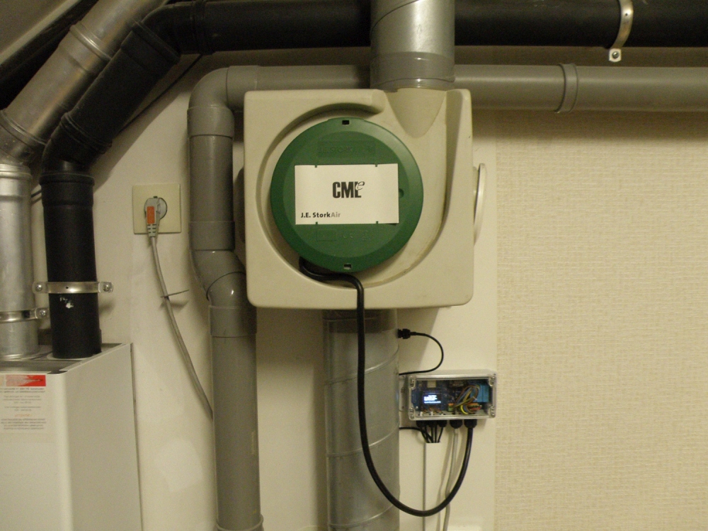
First of all I’m going to explain what a house extractor is used for. Because our houses are very well isolated (here in The Netherlands at least) we need some air flow to get rid off the polluted air in house and get some fresh oxygen in. The polluted air consists meanly cooking smell, co2, water vapor from showering and exhaling.
To accomplish this we have an central extractor (mechanische ventilator for our dutch readers).
Normally the extractor is always running on low speed and with the help of a switch in the kitchen you can put it in speed 2 or 3. There’s no way to switch it completely off.
To let my Joshua domotica Iot (internet of things) get control of the extractor I designed this hardware interface. With this interface and the help of Mqtt and Node-red you can control the extractor and still use the original switch in the kitchen to control it.
In the design I used 3 solid state relays so it’s also possible to switch the extractor completely off. With the help of node-red the extractor will be switched off when nobody is at home and the outside temperature is <18°C and the humidity in the bathroom is below 85%. Why? When nobody is at home the central heating system is also switched to a lower temperature with the help of node-red and Toon thermostat. To prevent that the house was cooling down (fast) due the extractor is switched off because this was sucking off the warmth.
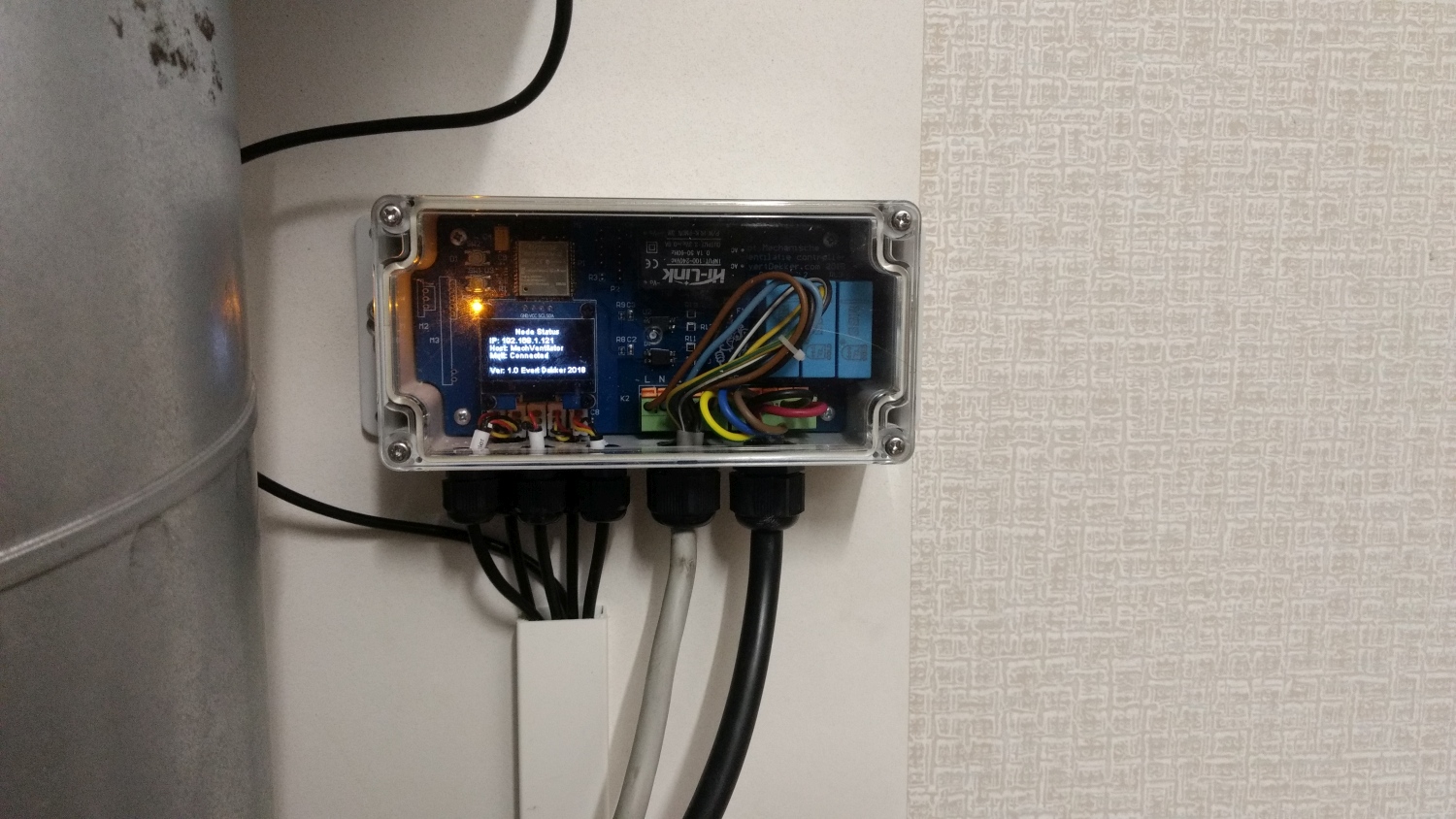
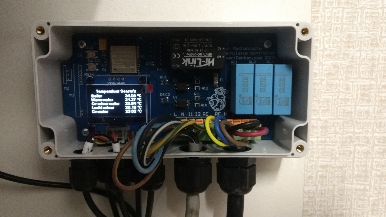
The Iot hardware interface was placed near the central heating system and solar collector it was also interesting to add some temperature sensors to measure different parameters and see what’s going on and eventually use this data in Node-red. 5 DS18B20 where added to measure these values.
The rest of the schematic is not that special the part regarding the mains is copied from my Iot light switch with mains input. Added a nice 1.3″ i2c o-led display for some feedback.
As you can see in the schematic and pcb there was also the plan to add 433Mhz receiver and transmitter to control the extractor with “klik aan klik uit”, however I don’t think this option is necessary anymore and leave it for what it is.
This was my first project that I use an ESP32 in the form of an Esp32-wroom32. The software development was all done in the Arduino ide and Sloeber ide.
What a lot of work was this. Because the Esp32 Arduino core and a lot of used library’s are still buggy I had to do a lot of debugging, scrolling to Github issues, open new issues and finding new library’s. The Esp32 was giving me a panic handler ones in a couple of days, connecting the serial port to a computer to log everything helped me to solve this. Then after updating the Arduino esp32 core to version 1.0.0 there where again new problems. Most of them where related to the dual core’s that where not working probably together with some library’s. Now it looks like it all working stable.
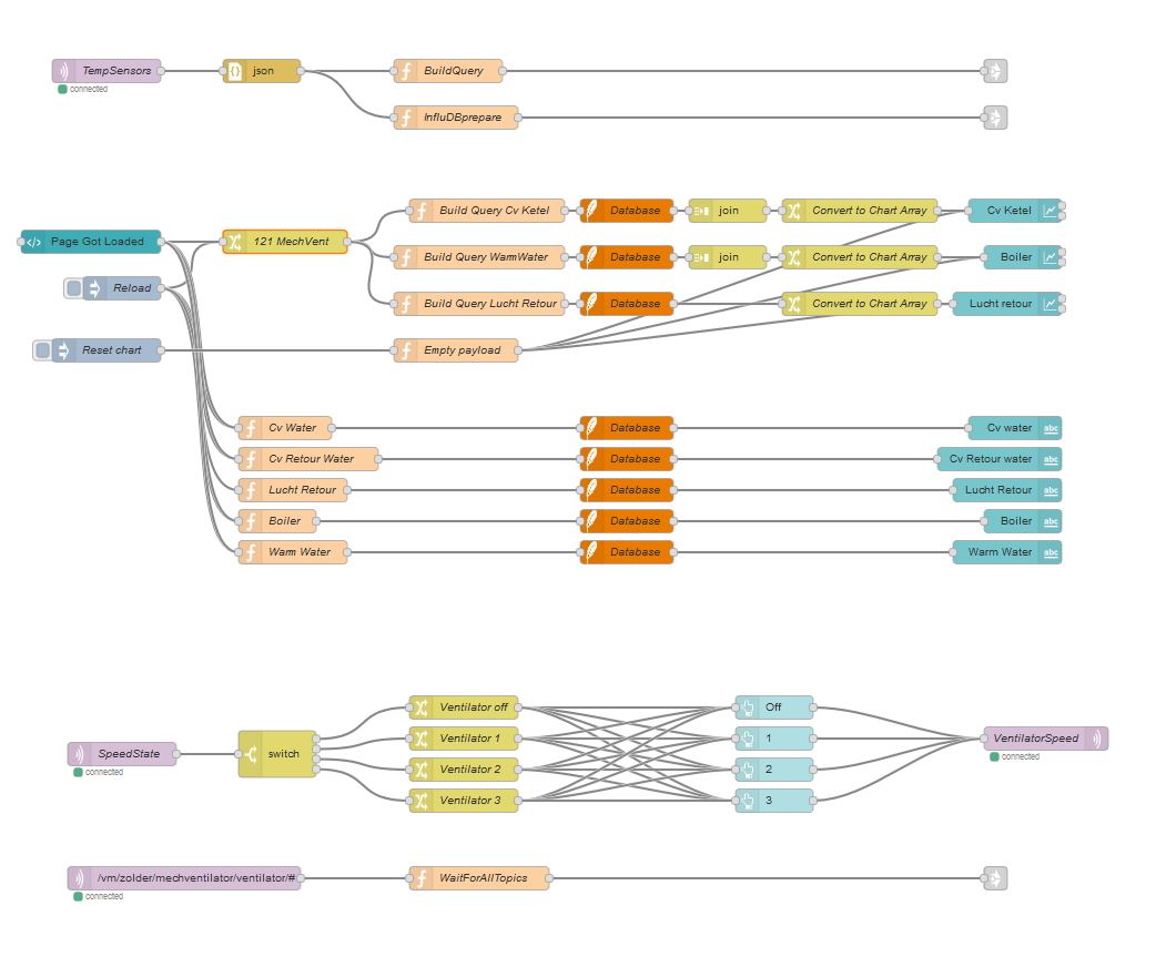
Below a screenshot from Node-red where all the data and functions for the extractor are handled. At the top the sensor data is stored in a SQlite and Influx database. In the middle the Node-red dashboard is build and data query from the SQlite database and shown in charts.
Below that we have the control over the extractor speed with left and right connection to the Mqtt broker.
And in the bottom flow the status of the extractor will be stored in the SQlite database.
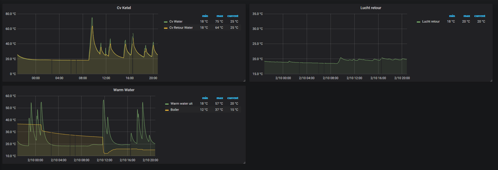
Here you can also see what amazing charts you can make with Grafana and Influx database.
I bought some (2pieces to start) PZEM-016 energy measure modules from Ali express. You can get them for around $8, not that expensive at all if you take in consideration what this device all can do. The idea was to measure in my fuse box all the groups (6) separately and push the data to my Mqtt broker over Wifi with the help of an Esp32 and Arduino.
As always the idea was born quick, but to get it all working together was a bit harder, partial because of faulty (not sure about that) manual, other bugs and even something stupid as a bad power supply. But, never give up and it’s now working fine.
The PZEM-014/016 can measure Ac voltage V, current A, active power W, frequency Hz, power factor pf and used energy Wh. You can read all these values from the PZEM with the help of a Rs-485 Half duplex bus. The protocol they used is the well known modbus protocol.
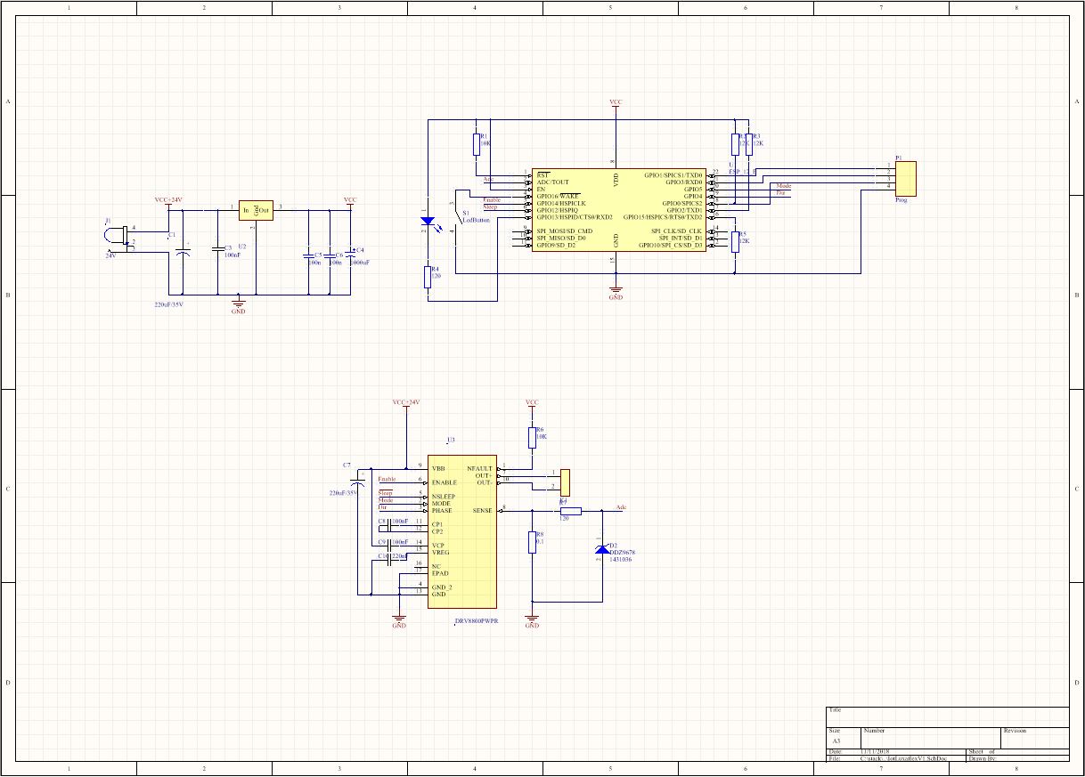
Note: The Rs485 side is safe, but the rest of the PZEM-014/016 has deadly mains voltage. Please be careful.
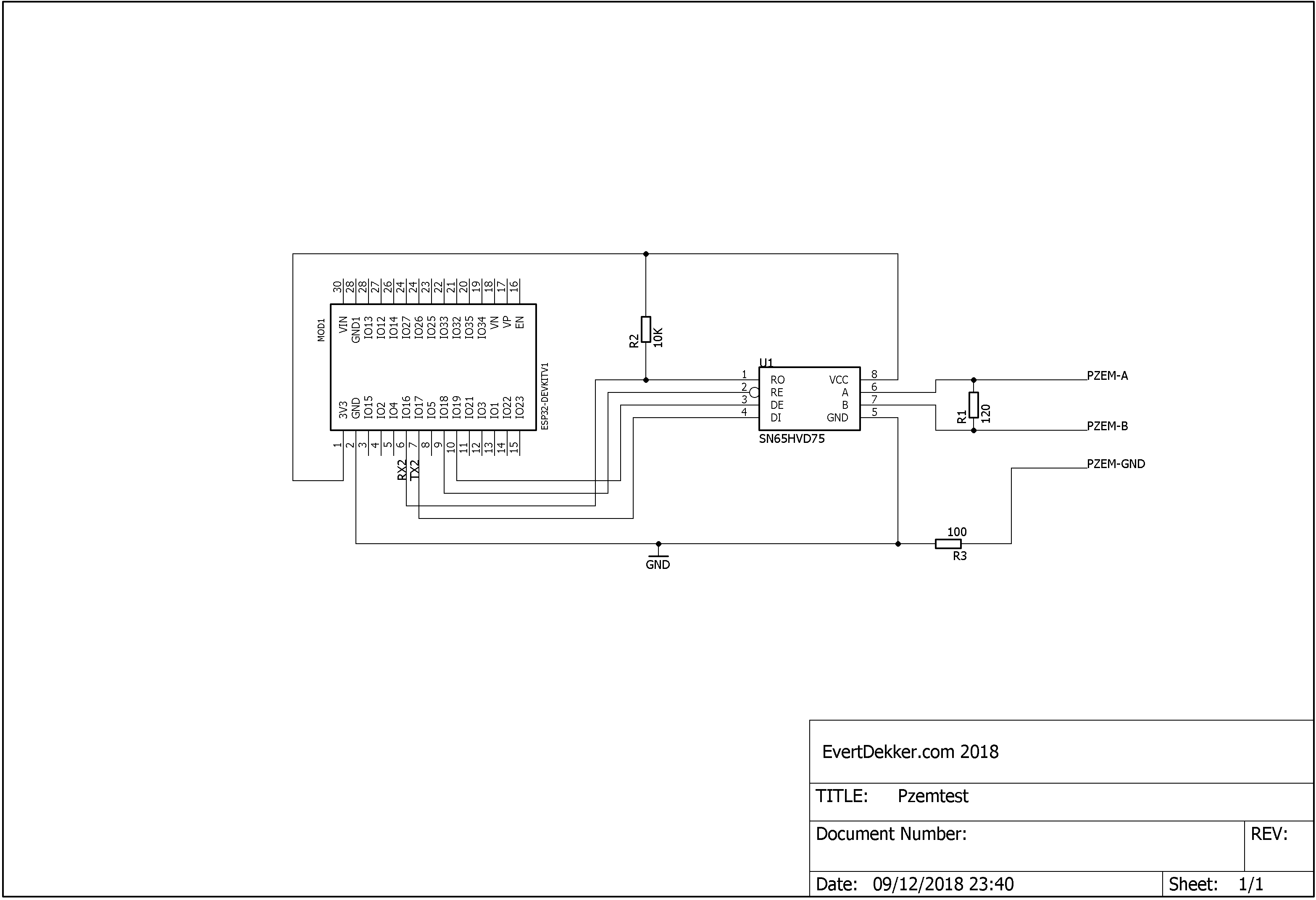
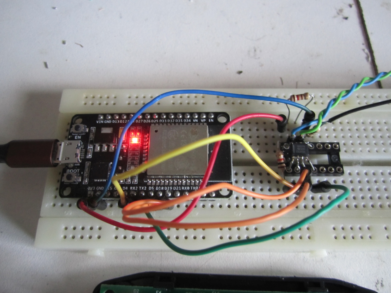
The schematic is not that special, if you worked before with Rs485 you will recognize the parts. As Rs485 line driver I used the SN65HVD75 from Texas Instruments, why? Because that’s the one I had on stock. You can use every Rs485 driver for it, however keep in mind that is should work with Vcc of 3.3V provided in the case by the ESP32 Devkit V1. The data in and out of the Rs4854 driver are connect to the 3e (uart2) hardware port of the Esp32. The data direction (RE_Not/DE) selectors are connected to 2 gpio of the Esp32. You can connected those pins also together to one gpio.
And now something about the RS485 bus.
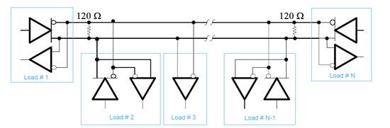
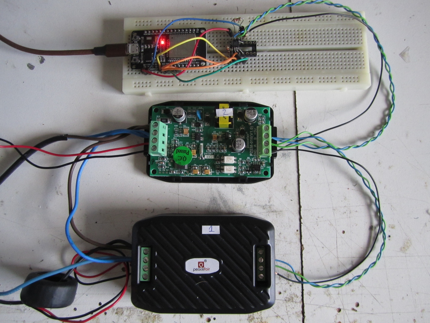
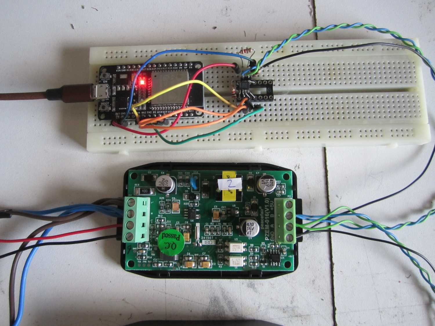
It’s important that you do this correct to get it all reliable. A good Rs485 has at the begin and the end of the line a termination resistor of 120Ω. So it doesn’t matter if you have 2 or 20 devices on the bus, you always need 2 termination resistors. Why, to get load on the line and prevent reflection of the signal. Google for it. You see in the schematic and the picture the termination resistor on the Rs485 driver in the breadboard. In the PZEM is a build in termination resistor that can’t be easy disabled, you need to solder it out. I have to test if a setup with 6 PZEM will work if you leave all the resistors, will come back to that if all my ordered PZEM are arrived and tested.
For the wiring of the Rs485 bus you need to use twisted cable, this will prevent interfering of the Rs485 signal by external sources. Read this if you want to know more theory. And then we have the ground wire for the network. it’s not necessary but my experience is that the network preforms not that good with long wires if you don’t use the ground wire. To prevent unwanted ground loop currents I have added a 100Ω resistor.
That was the hardware, let continue with the software. First we have to edit some files. If you are going to use uart1 or 2 on the esp32 you have to comment out some lines in esp32-hal-uart.c ;
If you are going to use the ModMaster library attached to this post, there’s no need to change this, it’s already done.
The Arduino code is commented and should be clear enough to get you going. In the code there’s a function called changeAddress , with this function you can change the slave address of the PZEM. Preferable you do this the best when only one PZEM is connected to the network. If you do something wrong or forgot the old slave address you can use the broadcast address 0xF8 to reset the address to a known number changeAddress(0xF8, 0x01). When using the broadcast address you must have only one slave connected. The other function resetEnergy will set the energy counter (Wh) back to zero.
One think that’s a bit strange and is (I think) as misprint in the manual and that’s the order of the crc bytes. The manual talks about Crc-highbyte first and then Crc-lowbyte. However this doesn’t work and with the help of sniffing the data between the PZEM014-Master software provided by Peacefair and the PZEM I found out that the crc order must be Crc-lowbyte first and then the Crc-highbyte. You can calculate very easy modbus crc here online.
Tested it all with an Esp32, but it should also work with an Esp8266 if you use the software uart and probably it works also with the other Arduino boards.
Schematic
Overview test setup
Detail Esp32 connections
Detail Pzm-015 connection
Note 27/7/2020: If the communication fails and you are using the PZEM-016 for the first time you must set the slave address first. You can do this with the tool provided by manufacturer or with the help of de Arduino code below by enable the line changeAddress and change it to changeAddress(0xF8, 0x01)
Download the Arduino Sketch and the modified ModbusMaster library.
/*
An Arduino Sketch for reading data from a PZEM-014 or PZEM-016, tested with ESP32 DEVKit 1, Arduino 1.8.5
EvertDekker.com 2018
If you want to use slaveid function to change the slaveid on the fly, you need to modify the ModbusMaster library (Or get the copy from my website)
In ModbusMaster.h add at line 78
void slaveid(uint8_t);
In ModbusMaster.cpp add at line 75
void ModbusMaster::slaveid(uint8_t slave)
{
_u8MBSlave = slave;
}
*/
/* If you are using other then uart0 on the ESP32, Comment out in esp32-hal-uart.c the follwing line:
//uart->dev->conf0.txfifo_rst = 1;
//uart->dev->conf0.txfifo_rst = 0;
//uart->dev->conf0.rxfifo_rst = 1;
//uart->dev->conf0.rxfifo_rst = 0;
Source: https://github.com/4-20ma/ModbusMaster/issues/93
*/
#include <ModbusMaster.h>
HardwareSerial Pzemserial(2);
#define RXD2 16 //Gpio pins Serial2
#define TXD2 17
#define MAX485_DE 19 // We're using a MAX485-compatible RS485 Transceiver. The Data Enable and Receiver Enable pins are hooked up as follows:
#define MAX485_RE_NEG 18
ModbusMaster node;
static uint8_t pzemSlaveAddr = 0x01;
void setup() {
Pzemserial.begin(9600, SERIAL_8N1, RXD2, TXD2); // Note the format for setting a serial port is as follows: Serial2.begin(baud-rate, protocol, RX pin, TX pin);
Serial.begin(9600);
node.begin(pzemSlaveAddr, Pzemserial); //Start the Modbusmaster
pinMode(MAX485_RE_NEG, OUTPUT); // Setting up the RS485 transceivers
pinMode(MAX485_DE, OUTPUT);
digitalWrite(MAX485_RE_NEG, 0); // Init in receive mode
digitalWrite(MAX485_DE, 0);
node.preTransmission(preTransmission); // Callbacks allow us to configure the RS485 transceiver correctly
node.postTransmission(postTransmission);
//changeAddress(0x01, 0x02);
/* By Uncomment the function in the above line you can change the slave address from one of the nodes, only need to be done ones. Preverable do this only with 1 slave in the network.
changeAddress(OldAddress, Newaddress)
If you f*ck it up or don't know the new address anymore, you can use the broadcast address 0XF8 as OldAddress to change the slave address. Use this with one slave ONLY in the network.
Note: First run of a new PZEM-016 you have to set the slave address first with: changeAddress(0xF8, 0x01)<br /><br /> */
//resetEnergy(0x01);
/* By Uncomment the function in the above line you can reset the energy counter (Wh) back to zero from one of the slaves.
*/
delay(1000);
}
/*
RegAddr Description Resolution
0x0000 Voltage value 1LSB correspond to 0.1V
0x0001 Current value low 16 bits 1LSB correspond to 0.001A
0x0002 Current value high 16 bits
0x0003 Power value low 16 bits 1LSB correspond to 0.1W
0x0004 Power value high 16 bits
0x0005 Energy value low 16 bits 1LSB correspond to 1Wh
0x0006 Energy value high 16 bits
0x0007 Frequency value 1LSB correspond to 0.1Hz
0x0008 Power factor value 1LSB correspond to 0.01
0x0009 Alarm status 0xFFFF is alarm,0x0000is not alarm
*/
void loop() {
uint8_t result;
for (pzemSlaveAddr = 1; pzemSlaveAddr < 3; pzemSlaveAddr++) { // Loop all the Pzem sensors
node.slaveid(pzemSlaveAddr); //Switch to another slave address. NOTE: You can only use this function is you have modified the ModbusMaster library (Or get the copy from my website)
Serial.print("Pzem Slave ");
Serial.print(pzemSlaveAddr);
Serial.print(": ");
result = node.readInputRegisters(0x0000, 9); //read the 9 registers of the PZEM-014 / 016
if (result == node.ku8MBSuccess)
{
uint32_t tempdouble = 0x00000000;
float voltage = node.getResponseBuffer(0x0000) / 10.0; //get the 16bit value for the voltage, divide it by 10 and cast in the float variable
tempdouble = (node.getResponseBuffer(0x0002) << 16) + node.getResponseBuffer(0x0001); // Get the 2 16bits registers and combine them to an unsigned 32bit
float current = tempdouble / 1000.00; // Divide the unsigned 32bit by 1000 and put in the current float variable
tempdouble = (node.getResponseBuffer(0x0004) << 16) + node.getResponseBuffer(0x0003);
float power = tempdouble / 10.0;
tempdouble = (node.getResponseBuffer(0x0006) << 16) + node.getResponseBuffer(0x0005);
float energy = tempdouble;
float hz = node.getResponseBuffer(0x0007) / 10.0;
float pf = node.getResponseBuffer(0x0008) / 100.00;
Serial.print(voltage, 1); // Print Voltage with 1 decimal
Serial.print("V ");
Serial.print(hz, 1);
Serial.print("Hz ");
Serial.print(current, 3);
Serial.print("A ");
Serial.print(power, 1);
Serial.print("W ");
Serial.print(pf, 2);
Serial.print("pf ");
Serial.print(energy, 0);
Serial.print("Wh ");
Serial.println();
} else
{
Serial.println("Failed to read modbus");
}
delay(1000);
}
}
void preTransmission() // Put RS485 Transceiver in transmit mode
{
digitalWrite(MAX485_RE_NEG, 1);
digitalWrite(MAX485_DE, 1);
delay(1);
}
void postTransmission() // Put RS485 Transceiver back in receive mode (default mode)
{
delay(3);
digitalWrite(MAX485_RE_NEG, 0);
digitalWrite(MAX485_DE, 0);
}
void resetEnergy(uint8_t slaveAddr) //Reset the slave's energy counter
{
uint16_t u16CRC = 0xFFFF;
static uint8_t resetCommand = 0x42;
u16CRC = crc16_update(u16CRC, slaveAddr);
u16CRC = crc16_update(u16CRC, resetCommand);
Serial.println("Resetting Energy");
preTransmission();
Pzemserial.write(slaveAddr);
Pzemserial.write(resetCommand);
Pzemserial.write(lowByte(u16CRC));
Pzemserial.write(highByte(u16CRC));
delay(10);
postTransmission();
delay(100);
while (Pzemserial.available()) { // Prints the response from the Pzem, do something with it if you like
Serial.print(char(Pzemserial.read()), HEX);
Serial.print(" ");
}
}
void changeAddress(uint8_t OldslaveAddr, uint8_t NewslaveAddr) //Change the slave address of a node
{
static uint8_t SlaveParameter = 0x06;
static uint16_t registerAddress = 0x0002; // Register address to be changed
uint16_t u16CRC = 0xFFFF;
u16CRC = crc16_update(u16CRC, OldslaveAddr); // Calculate the crc16 over the 6bytes to be send
u16CRC = crc16_update(u16CRC, SlaveParameter);
u16CRC = crc16_update(u16CRC, highByte(registerAddress));
u16CRC = crc16_update(u16CRC, lowByte(registerAddress));
u16CRC = crc16_update(u16CRC, highByte(NewslaveAddr));
u16CRC = crc16_update(u16CRC, lowByte(NewslaveAddr));
Serial.println("Change Slave Address");
preTransmission();
Pzemserial.write(OldslaveAddr);
Pzemserial.write(SlaveParameter);
Pzemserial.write(highByte(registerAddress));
Pzemserial.write(lowByte(registerAddress));
Pzemserial.write(highByte(NewslaveAddr));
Pzemserial.write(lowByte(NewslaveAddr));
Pzemserial.write(lowByte(u16CRC));
Pzemserial.write(highByte(u16CRC));
delay(10);
postTransmission();
delay(100);
while (Pzemserial.available()) { // Prints the response from the Pzem, do something with it if you like
Serial.print(char(Pzemserial.read()), HEX);
Serial.print(" ");
}
}
8 March 2020 deprecated Tweaknews switched to another vpn provider, Privado. This provider support vpn connections from other devices then only windows.
In the support section there’s enough information to get your vpn running from Android, Linux, Mac and other devices. This will make the work around as described below deprecated.
TweakNews is a usenet provider that’s not that expensive and in some of there plans you have also the possibility to use vpn.
To use vpn they have a app for Windows, Android and Apple. Not for Linux! Wtf, almost all Nas are running on Linux, routers are running on linux, Raspberry runs on Linux, etc…
I’m not gone explain how to install OpenVpn on your device, there are enough tutorials on the net for the device you have to explain that. This post will only help you with the required OpenVpn files for Tweaknews.
I did some “reverse” engineering with the Windows app and luckily they are using OpenVpn as base for the app.
If you install the windows app all required info can be found in the c:\Program Files (x86)\TweakNews\OpenVPN\ directory.
The openvpn.config and tweaknews.crt file are there, you don’t need more to get OpenVpn working.
To make it easier I have combined those 2 files to TweakNews.ovpn for easy importing the settings in Openvpn, you can download it below.
In this file you find on line 3 the Vpn server where you will connect to, in this case to the server in The Netherlands.
To find out ip addresses for other country’s, run the Tweaknews app ones on a Windows desktop and check the openvpn.config file. Share you country and Ip address in the comment below for other users.
After making connection with the server it will ask for the user name and password. For the username you must use your TweakNet login name and add @tweaknews to it at the end, for example tw1234567@tweaknews. Password is the same as you always use with your Tweaknews account.
This is a renewed and updated version of my blinds controller. With this controller we can lower and raise the horizontal Luxaflex blinds. This controller was one of the first devices in my Joshua Domotica and the controller for one of the bedrooms needed to be replaced.
Just like my previous Esp8266 and Esp32 domotica projects it will connect through Mosquitto with Node-red. With the help of Node-red we can control the blinds and do almost everything we want with it.
The hart of the design is the Esp8266 and a DRV8800 full bridge motor driver. With the h-bridge we can control the direction that the 24V motor of the blinds will turn and therefore lower or raise the blinds .
With the help of the Enable pin and pwm (pulse wide modulation) it’s possible to let motor run on lower speed to tilt the blinds for example half way the window.
Because the motor requires 24V to operate and the Esp8266 only 3.3V we needed a buck convertor to step down the 24V with a minimum of loss to 3.3V. For this buck convertor I simply bought a ready made one from Ali express.
To suppress the inrush current for the motor some electrolytic capacitors were added to prevent the Esp8266 for resetting due to a dip in the power supply. Note: In the schematic C4 has a value of 1000µF, but this should be just like C1, 220µF. Btw the value of R8 is also incorrect, see below. I really should update my schematics sooner and better.
Because the blinds doesn’t have end switches or other feedback, the only way to determine where they are is the time when the motor is running and in what direction, it’s mostly done by the software. To determine if the motor runs there’s a current sense resistor added to the DRV8800. Over this resistor is an 1.8V zenerdiode mounted to prevent to high voltage on the analog input of the Esp8266.
The 1Ω resistor on the photo is replaced with a 0.5Ω 1210 resistor because the DRV8800 was not working with 1Ω. According to the datasheet this will exceed the maximum sense voltage.
You read those things in the datasheet after you find out it’s not working correct. Due to the smaller resistor the voltage drop is also smaller and it’s not possible anymore to use the full AD range of 1V of the Esp8266. We can still detect if the motor is running or not, but in a next design there should be an op-amp added to amplify the signal.
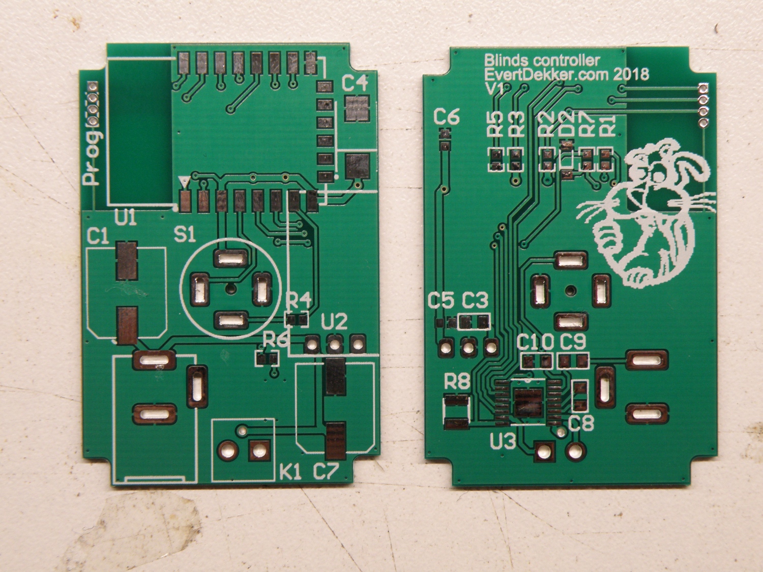
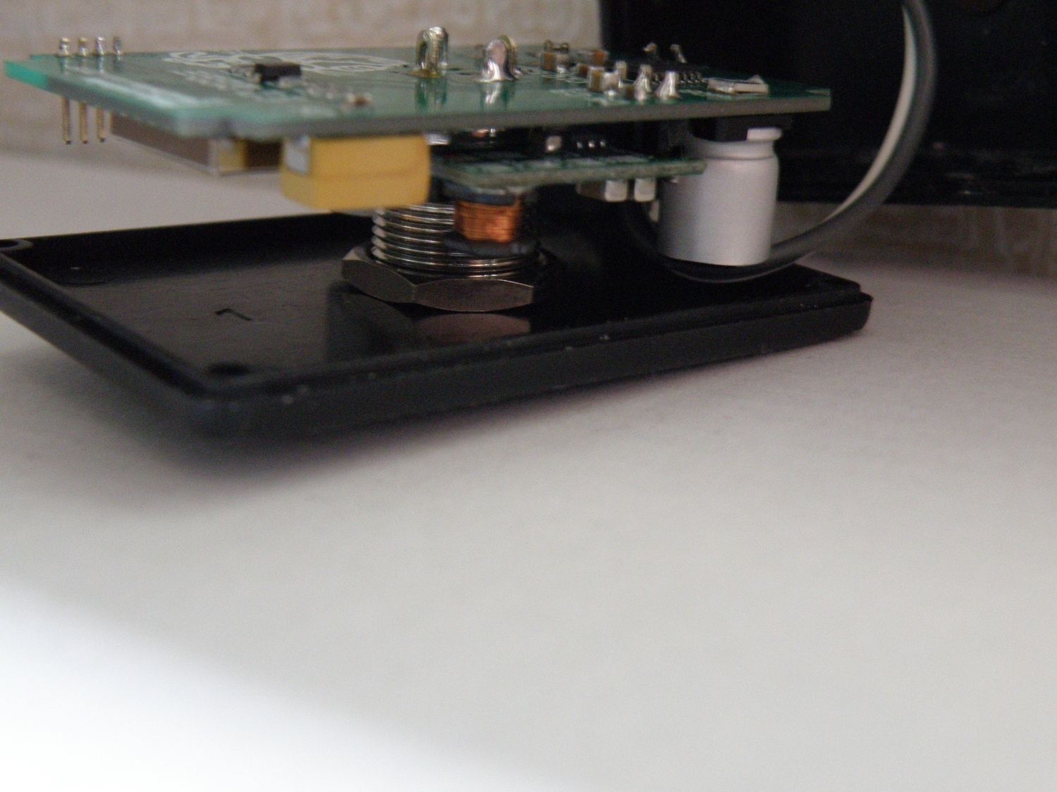
The pcb was designed very compact. I bought a small box 53x35x23mm and made the pcb to fit exactly in this box. The pcb is mounted on the back of the switch to make it one and save some space for mounting holes. The pcb is 1mm thick to save also some space in the height. Very nice design if I may say so.
Schematic
Bare pcb
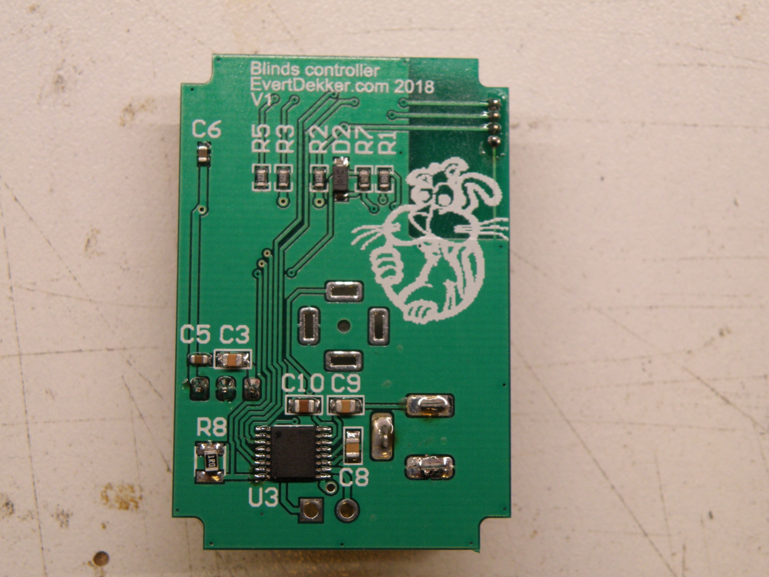
Finished pcb back
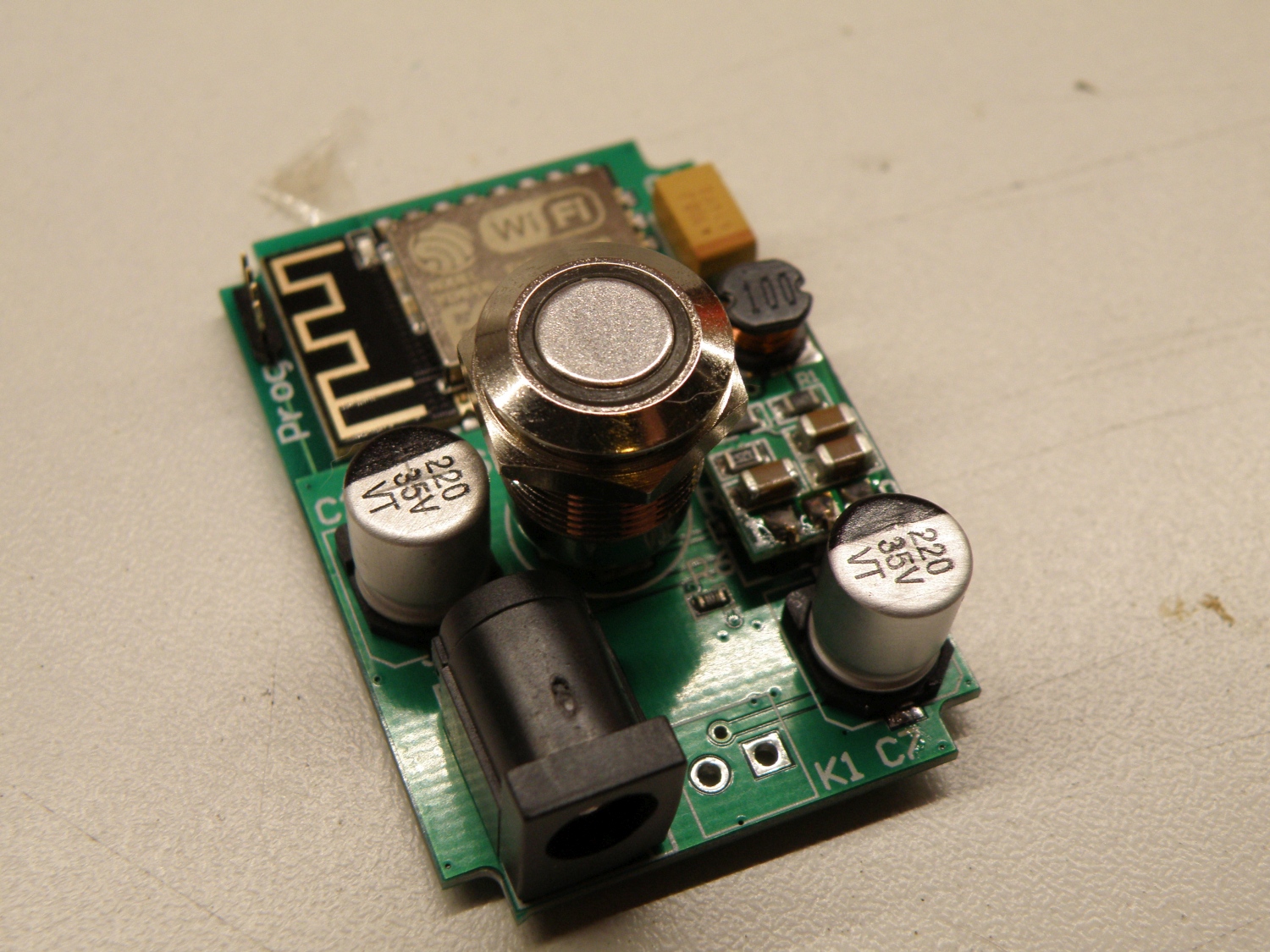
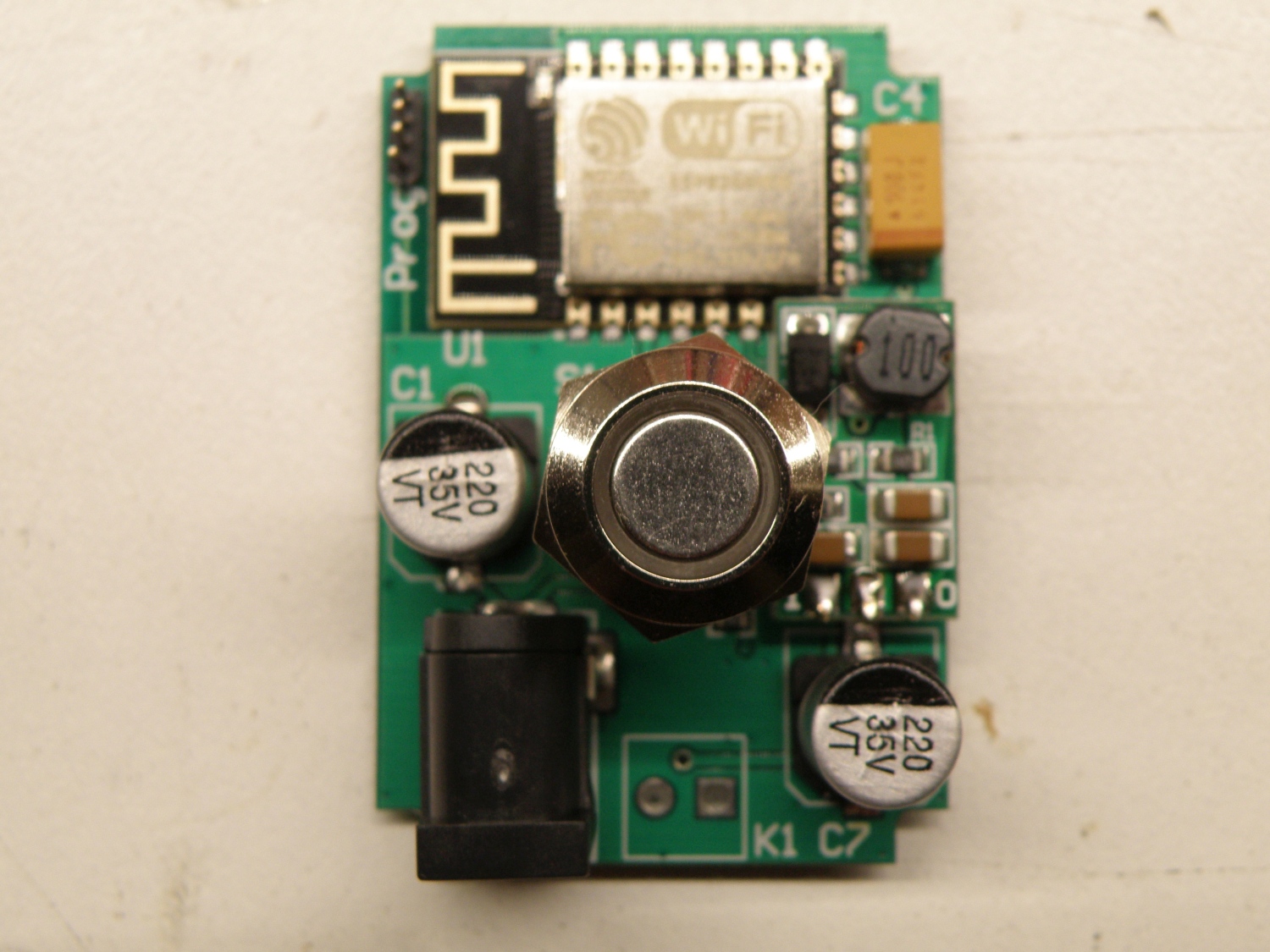
Finished pcb front
Finished pcb front 2
Pcb in enclosure
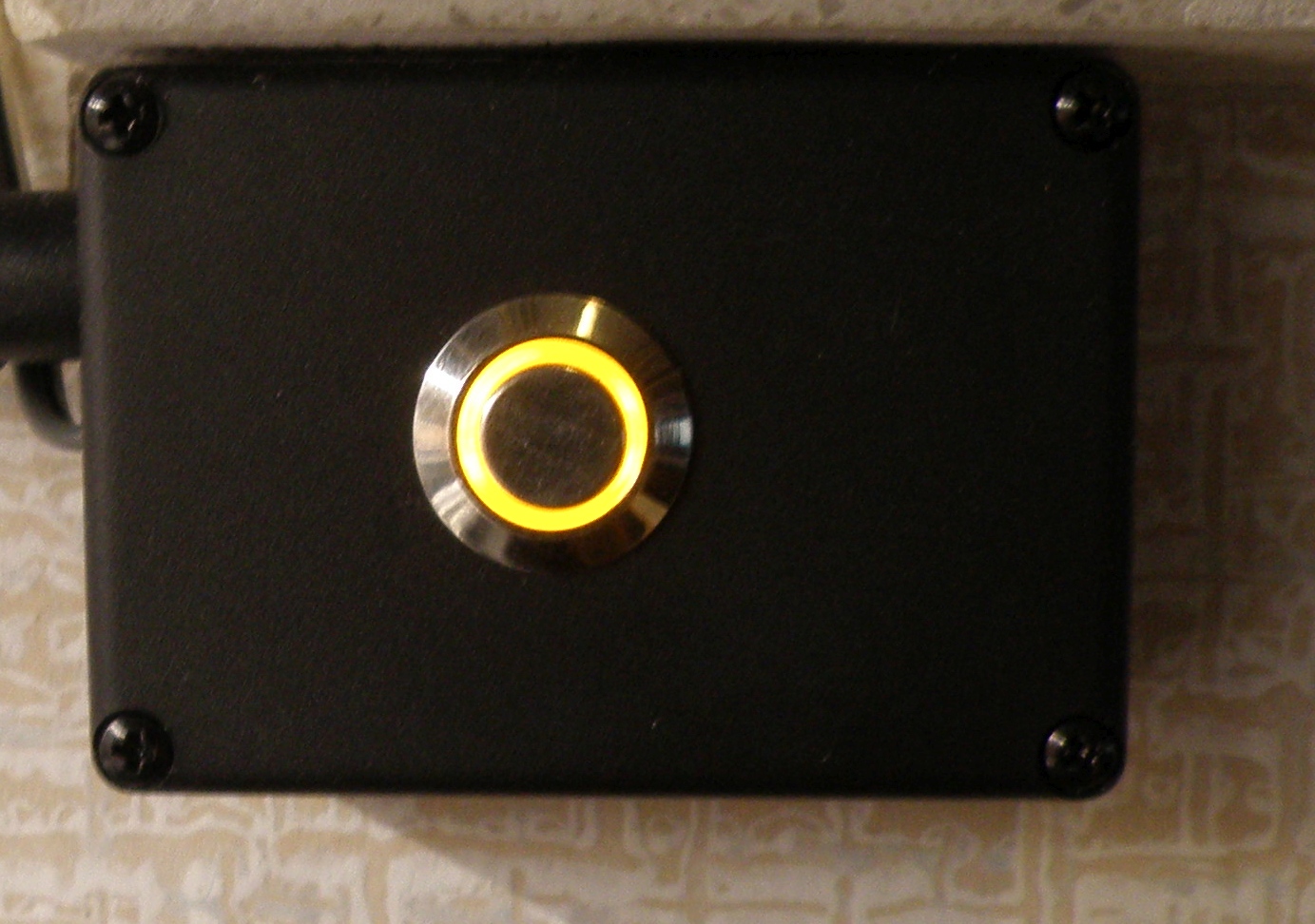
Finished enclosure front with iluminated button
Demo Blinds Controller
If want to make your own, or use some parts from the design, here are the Altium 16 design files.
We use cookies to ensure that we give you the best experience on our website. If you continue to use this site we will assume that you are happy with it.