Oldies Joshua Predecessor
The predecessor of my Joshua Domotica , here’s a more detailed overview of the electronics used.
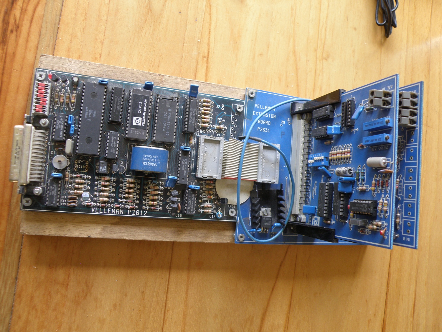
Joshua predecessor controller board
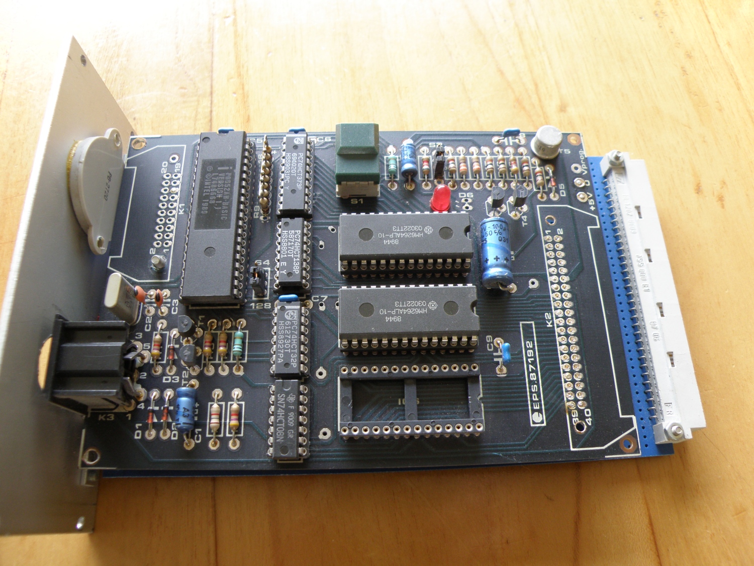
First controller board for my domotica. Was running on a 8052AH Basic and mounted in a 19″ rack with the other eurocards. Not in use anymore, everything can now be done with a simple avr controller.
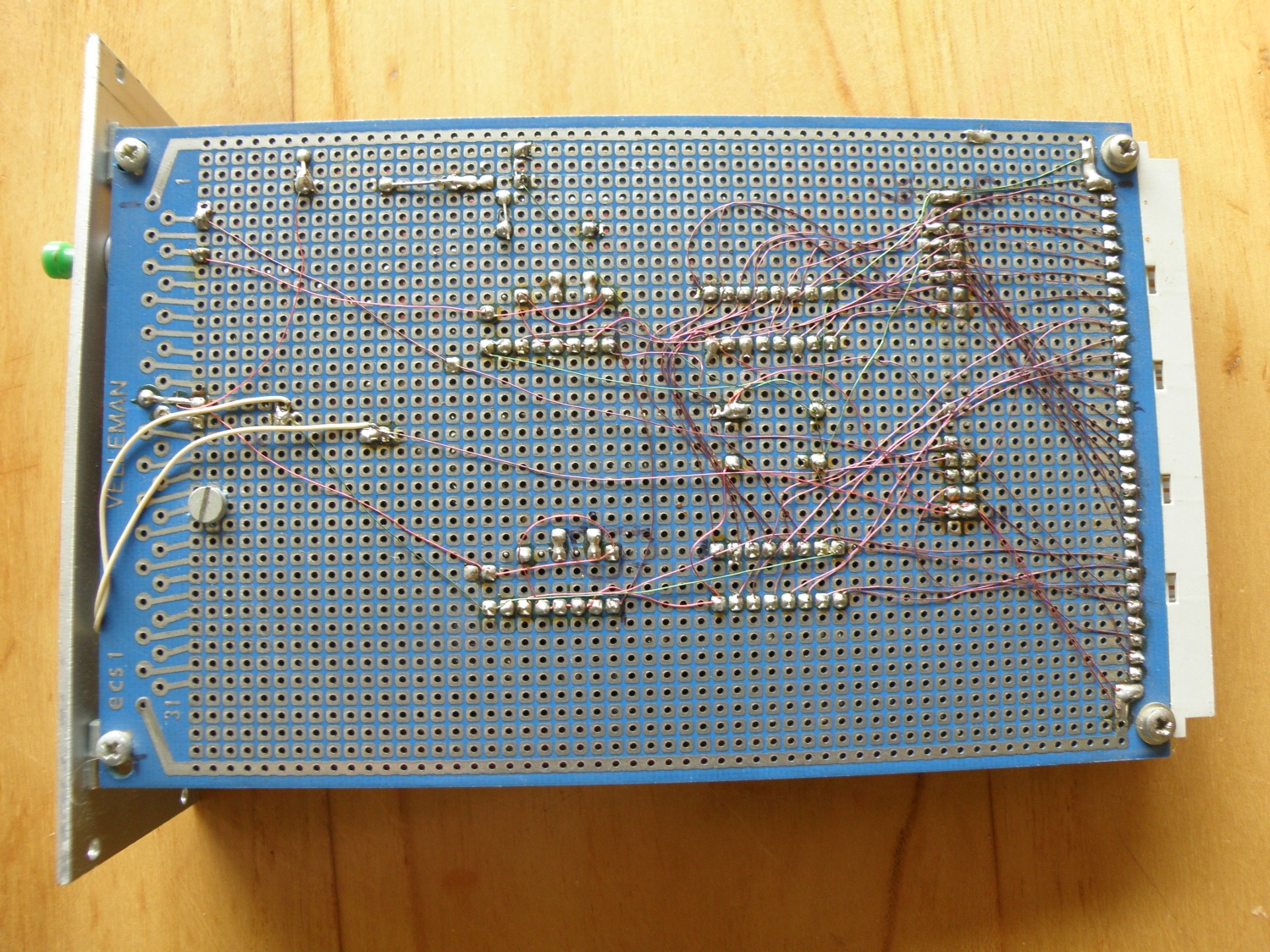
Same board controller board, bottom view.
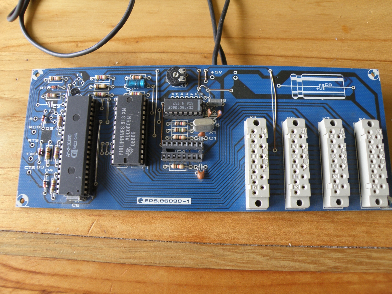
96 channel Ir-receiver board
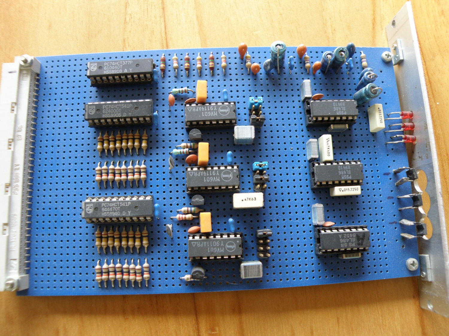
Ir receiver board to belongs to the above Joshua predecessor controller board. A lot of electronics for something simple we now these days with one receiver and the rest in software.
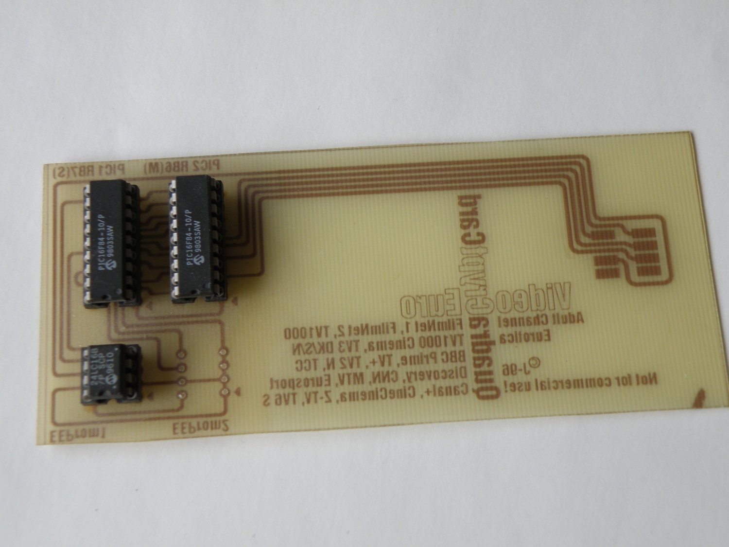
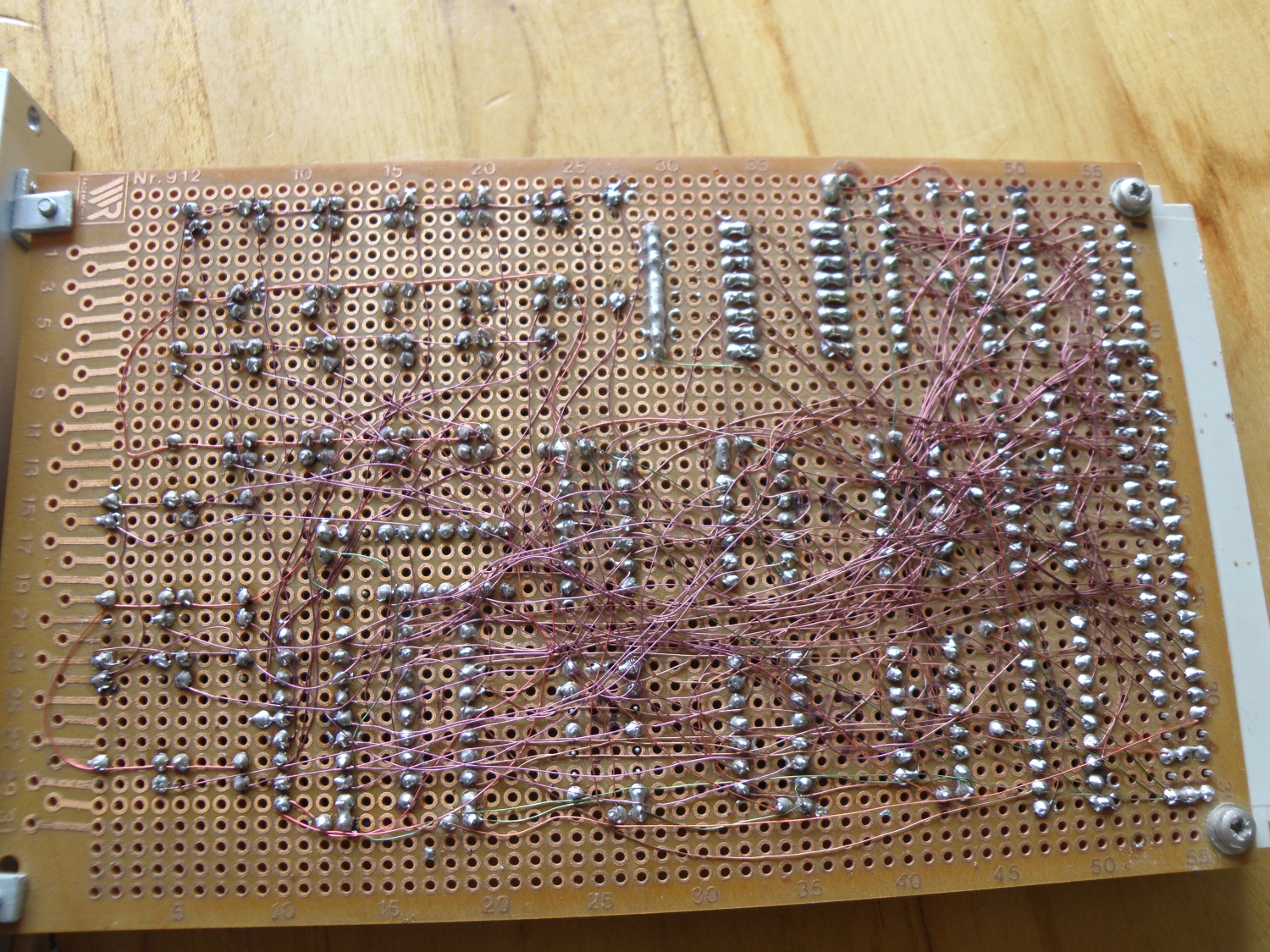
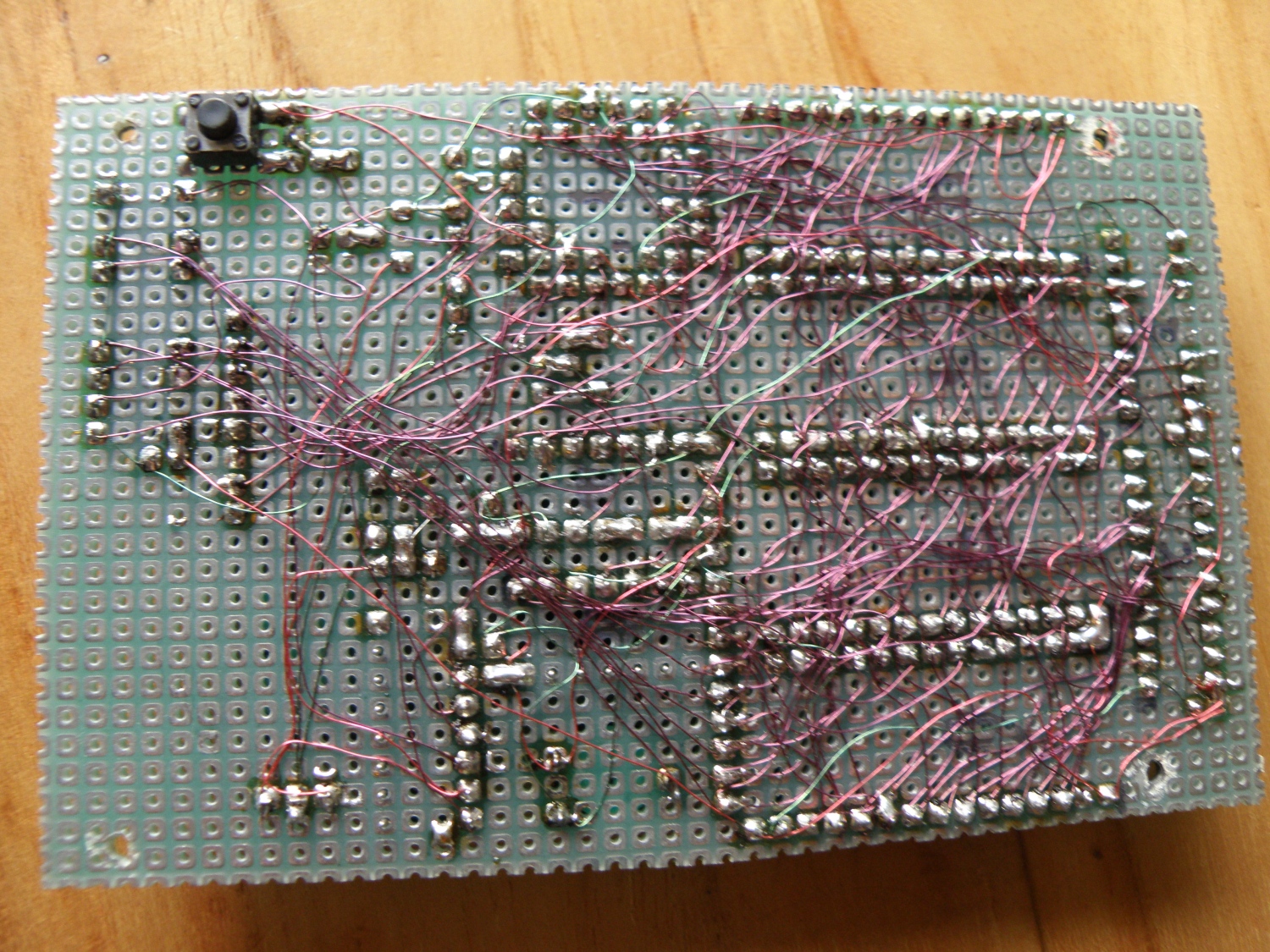
Same ir receiver board, bottom view. Routing and making a pcb was 25 years ago not that easy and cheap so wiring the pcb with roadrunner wire was the simplest and cheapest way to make the pcb. Until you made a mistake…
You can’t see it anymore but there where different colors for Vcc, gnd and data, but after all those years the colors are faded.
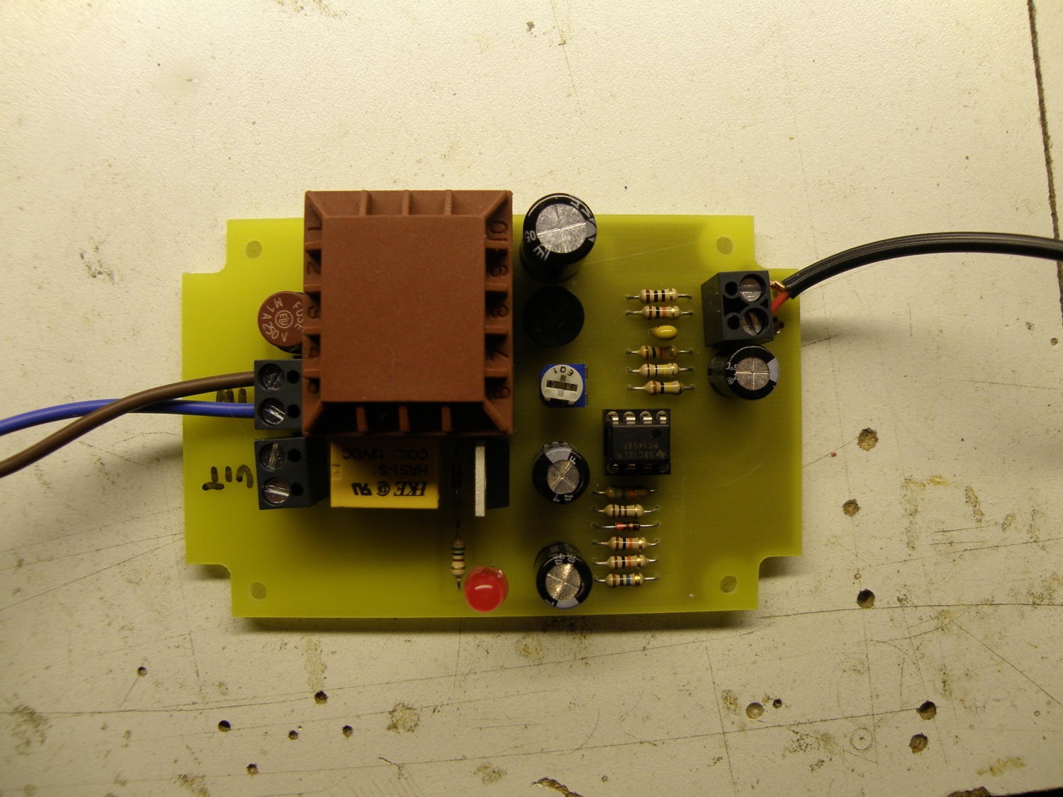
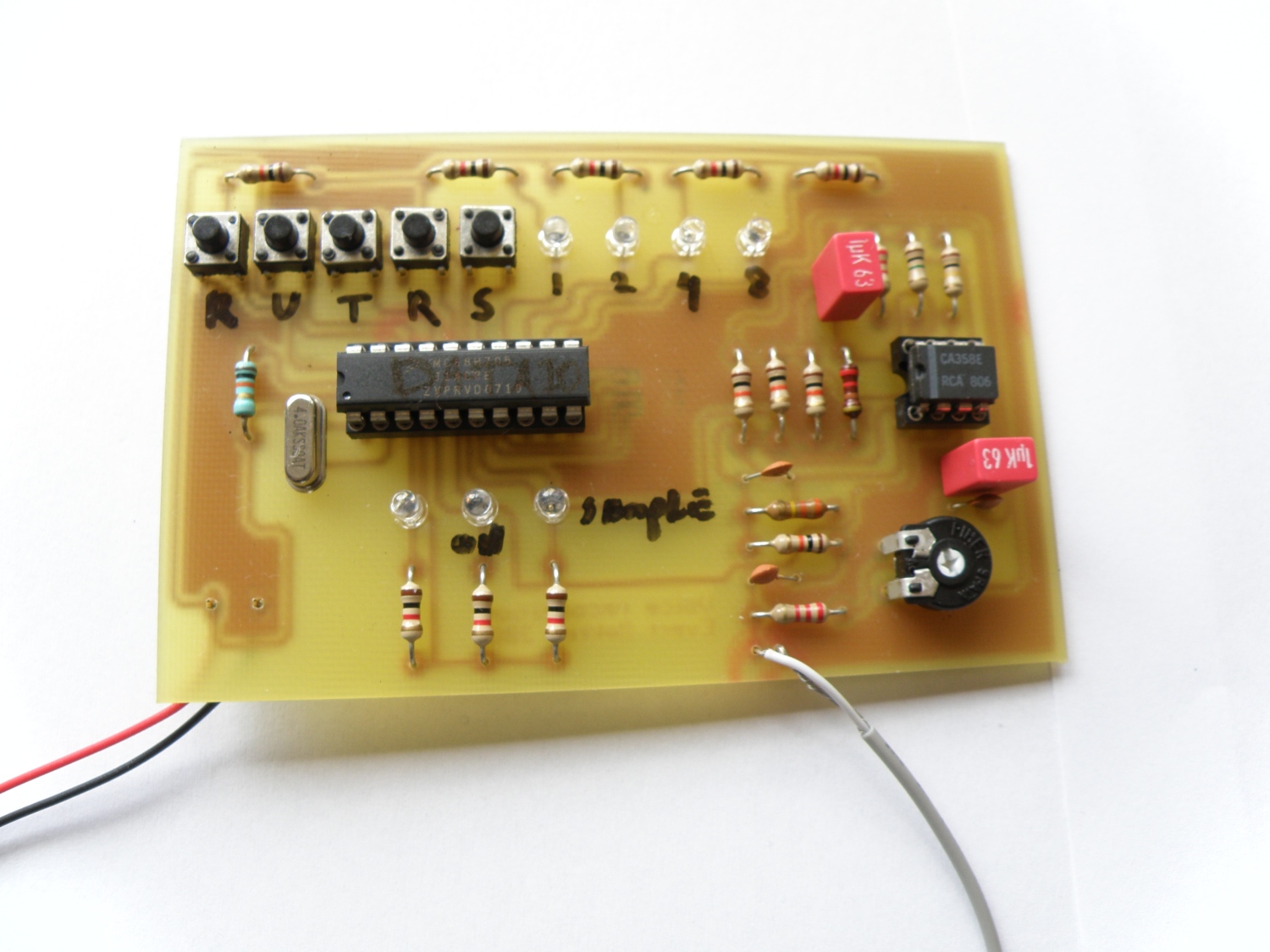
Ir Transmitter
![]()
The ir transmitter for the above receiver board. I used it only to program my learning remote controller, so that’s why it’s not build for daily use. You can switch between 3×32 channels with the jumpers.
![]()
The original Elektor design only supported 10 channels so I hacked in the other 22 channels that the Ir controller was capable of sending by adding my own keyboard.
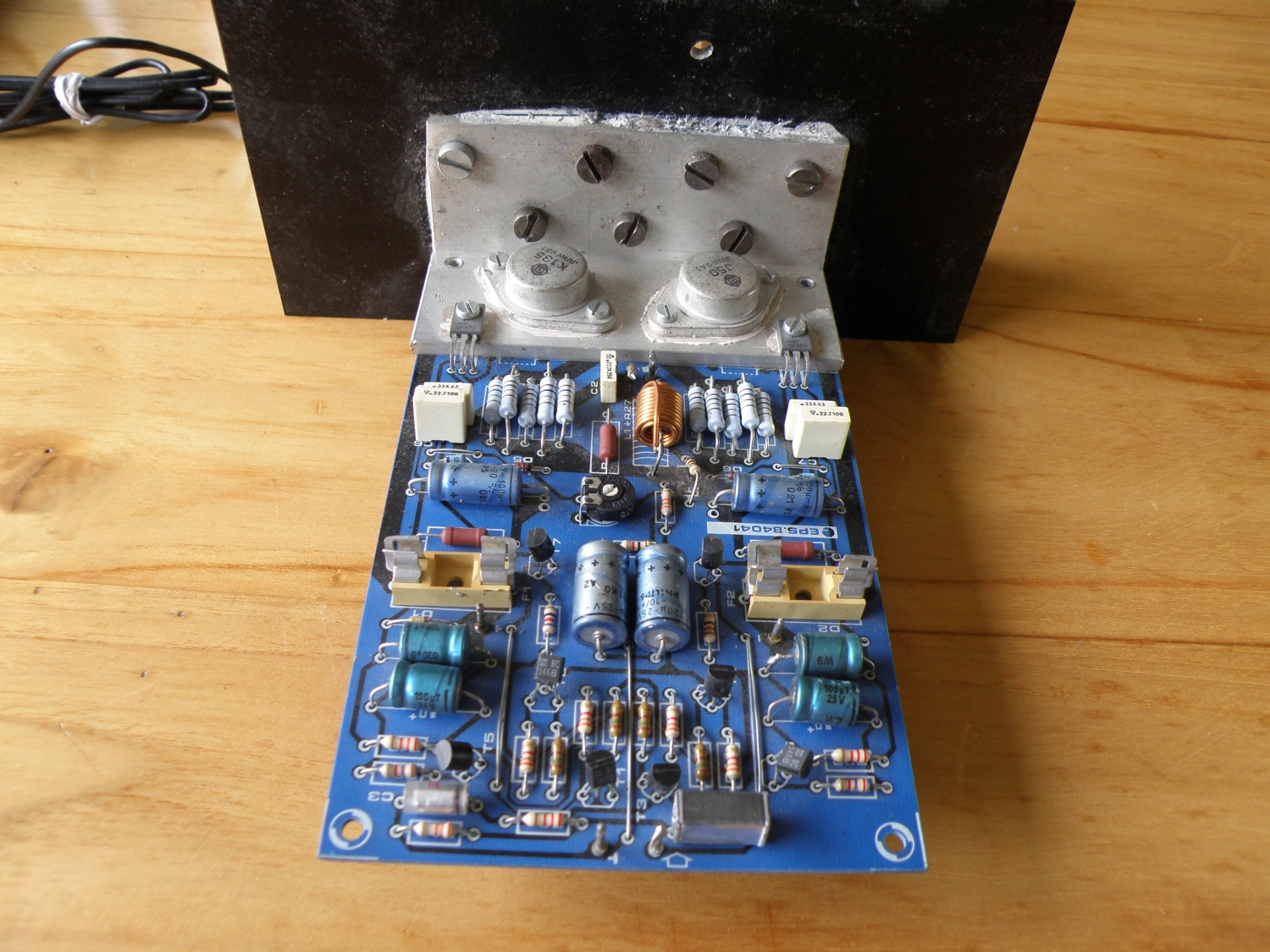
Amplifier interface
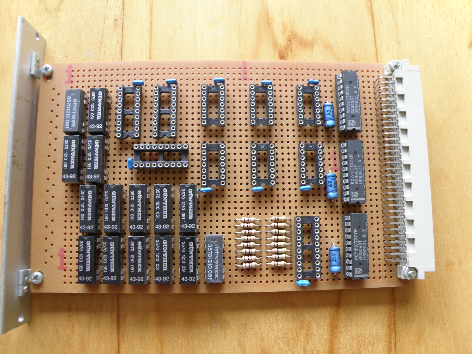
The interface card between my domotica and amplifier. Looking at the empty sockets I have already recycled some ics.
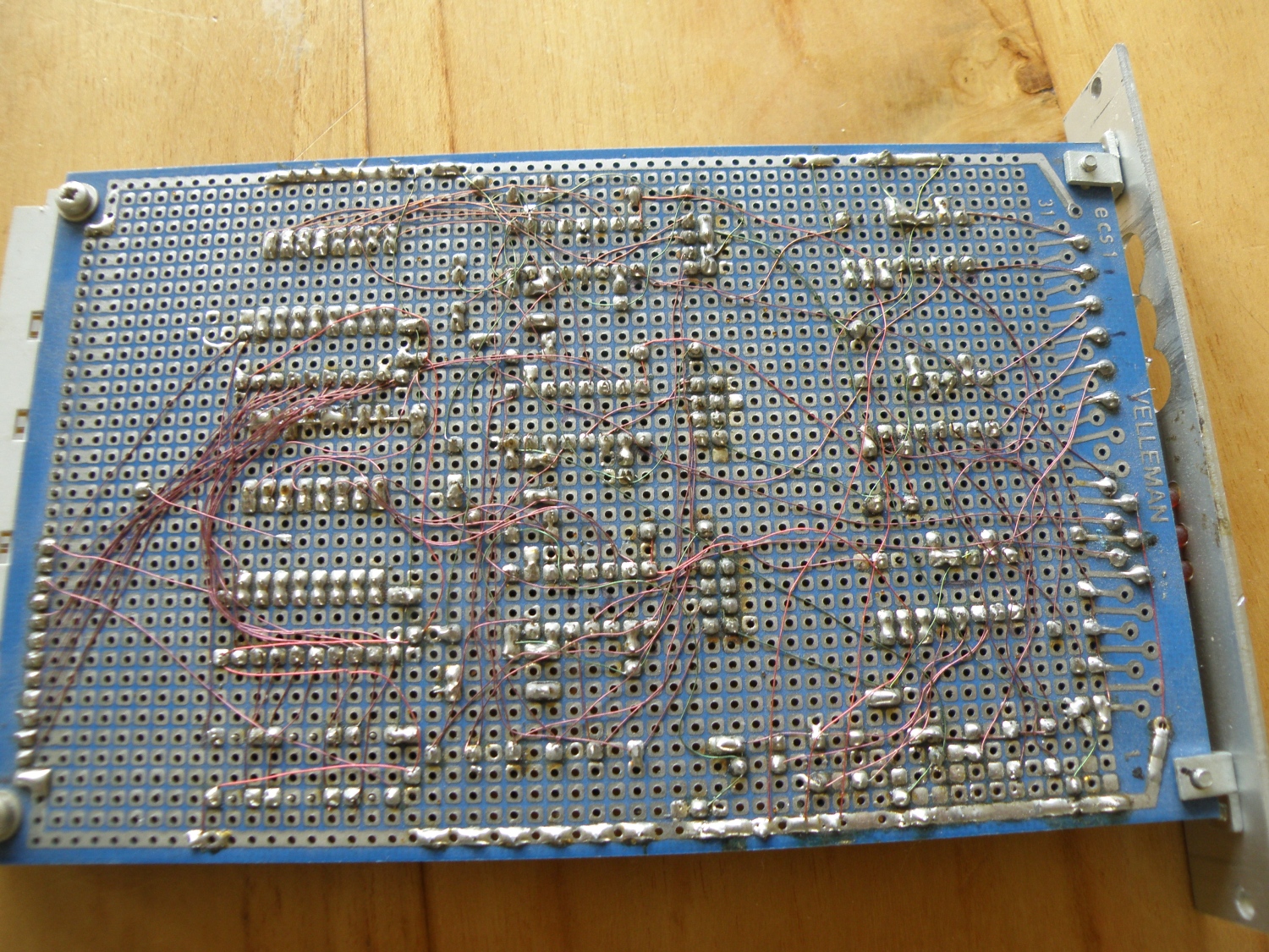
And on the back side again a lot of roadrunner wires.
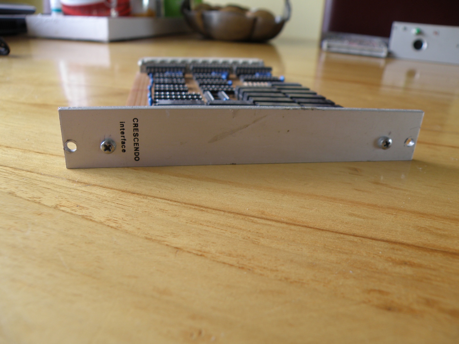
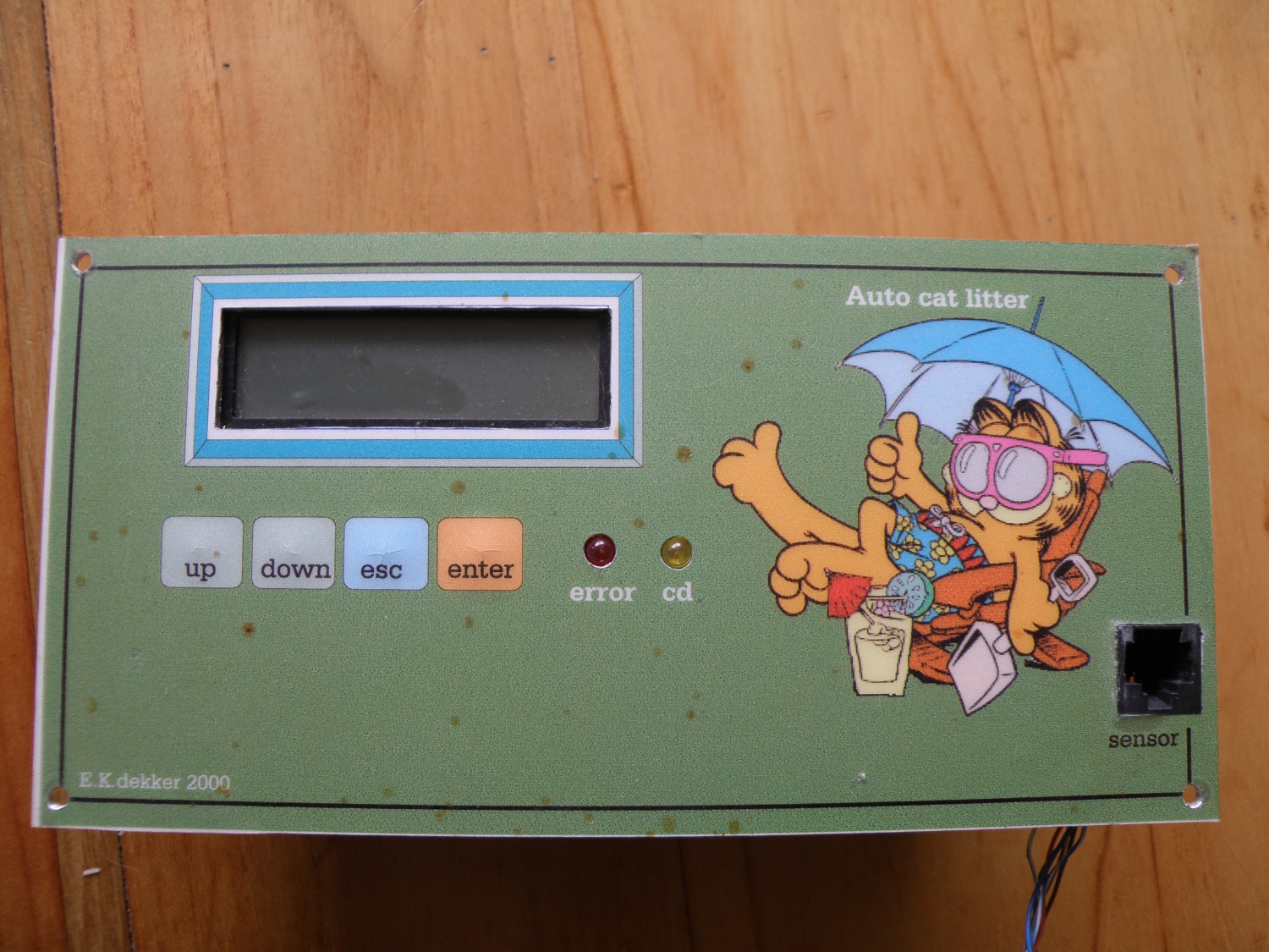
From this interface board also a picture of the frontpanel.
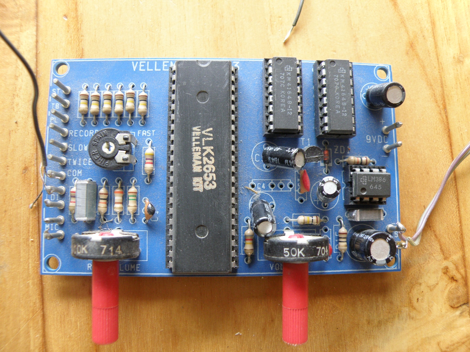
Speech card
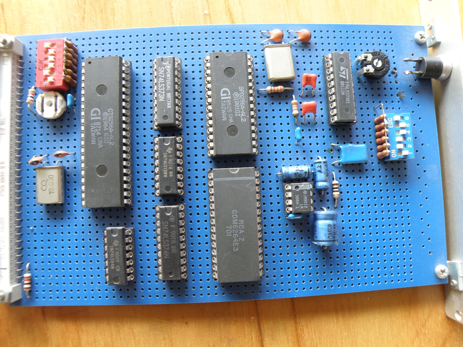
And the speech card, based on the Sp0256A and the CTS256A processor. We had a lot of fun with this speechcard. Nobody understood what was said and I didn’t get that, I understood everything that was coming out of the speaker. Looks like because me as the programmer did know what speech there was expected and therefore understood it all.
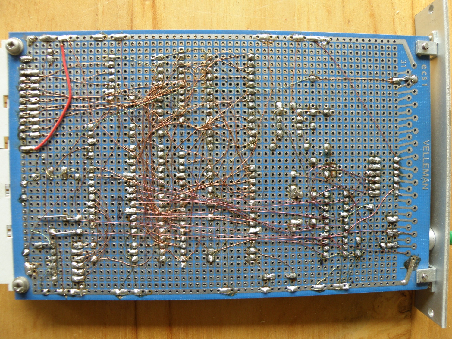
Backside with all the roadrunner wires again.
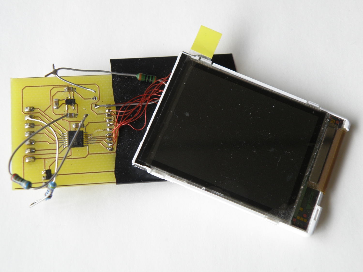
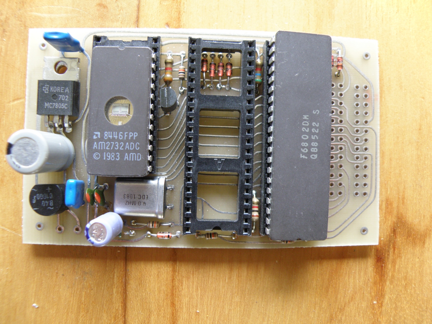
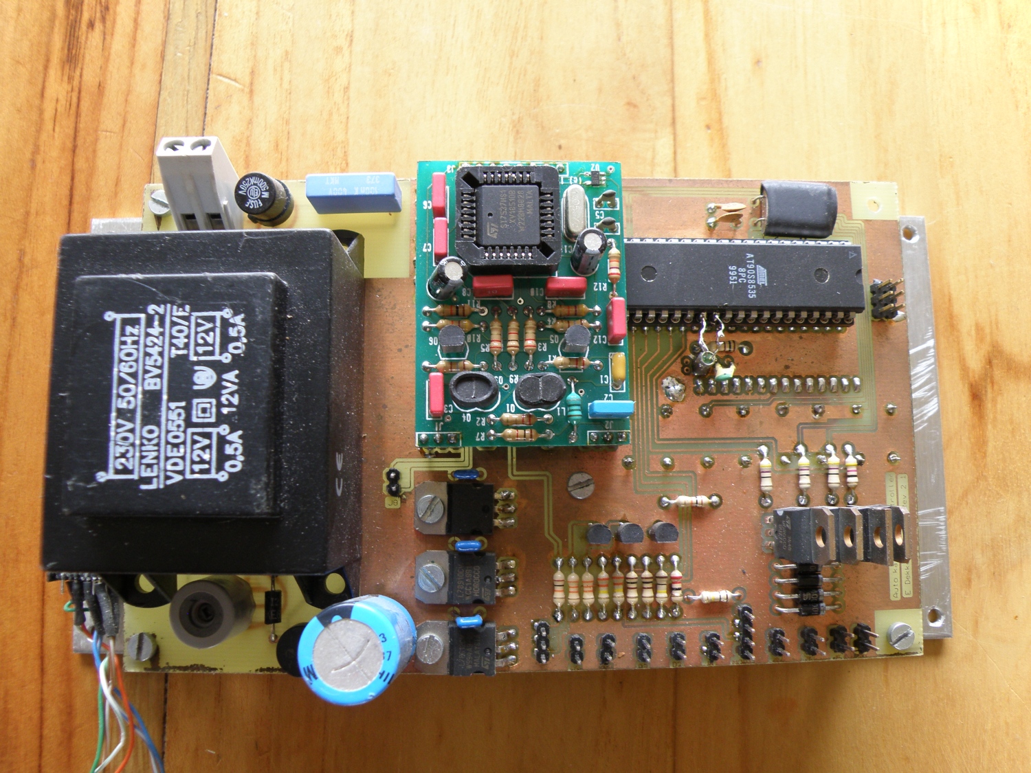
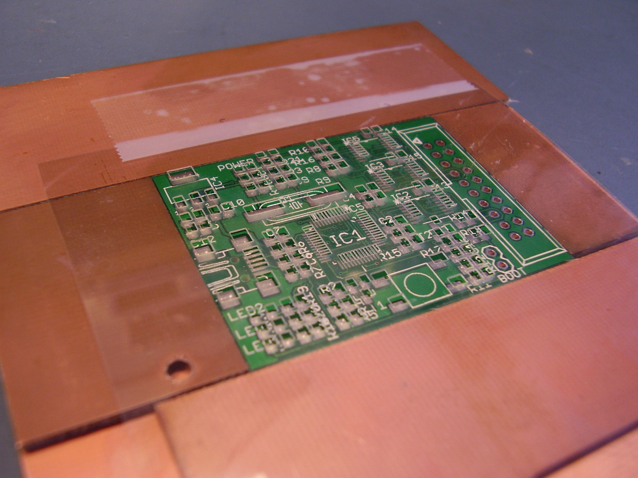
Rf Remote
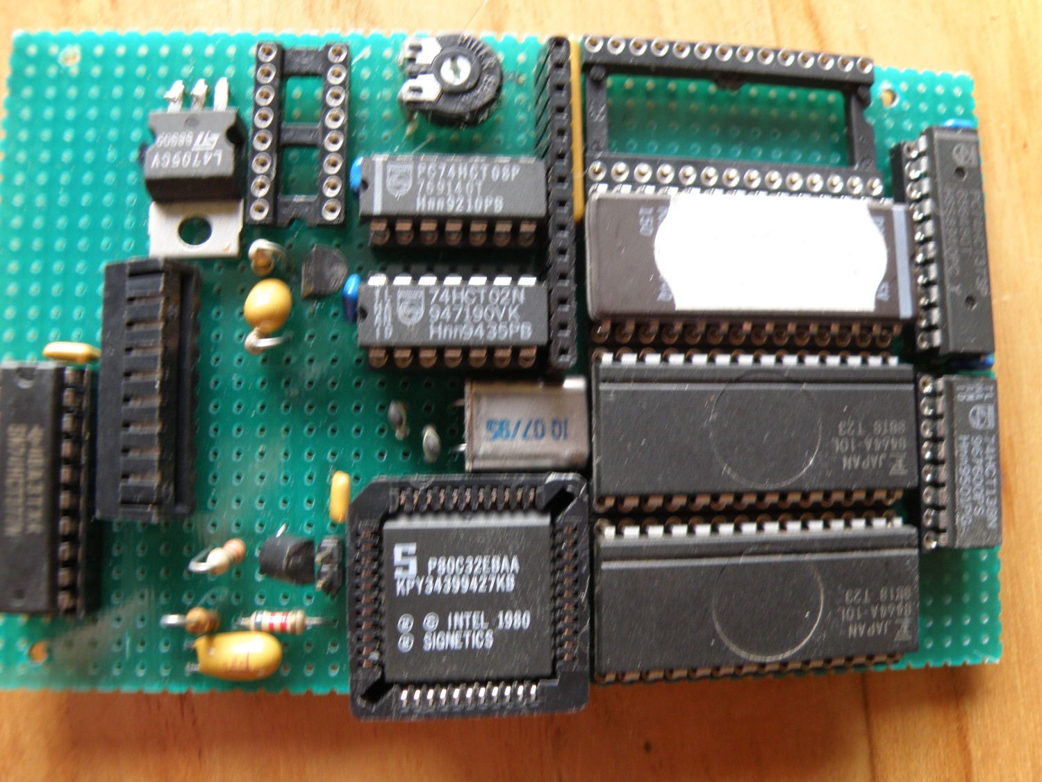
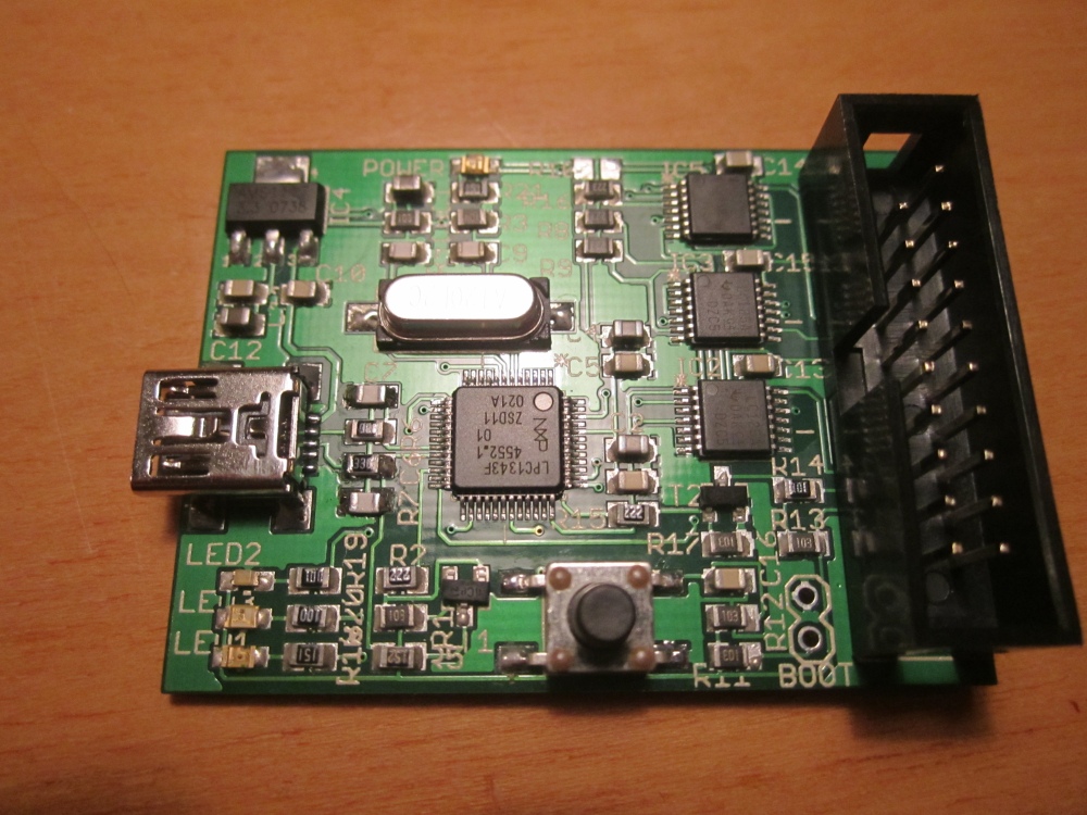
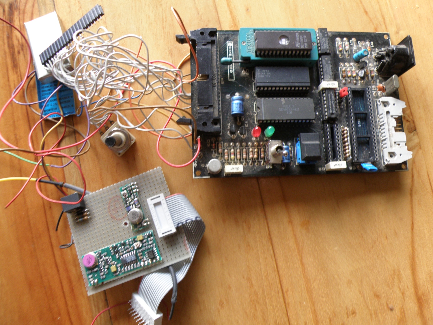
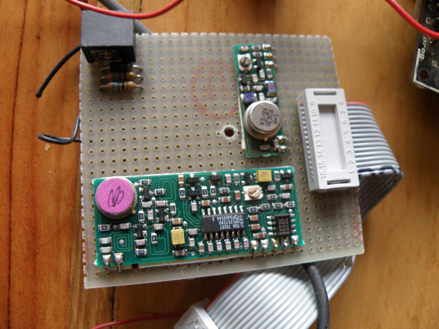
I had someday a crazy idea to make a Rf remote control for the Joshua predecessor. This was begin of the ’90 when it was a bit complicated then now a days. This is the test setup to develop the software.
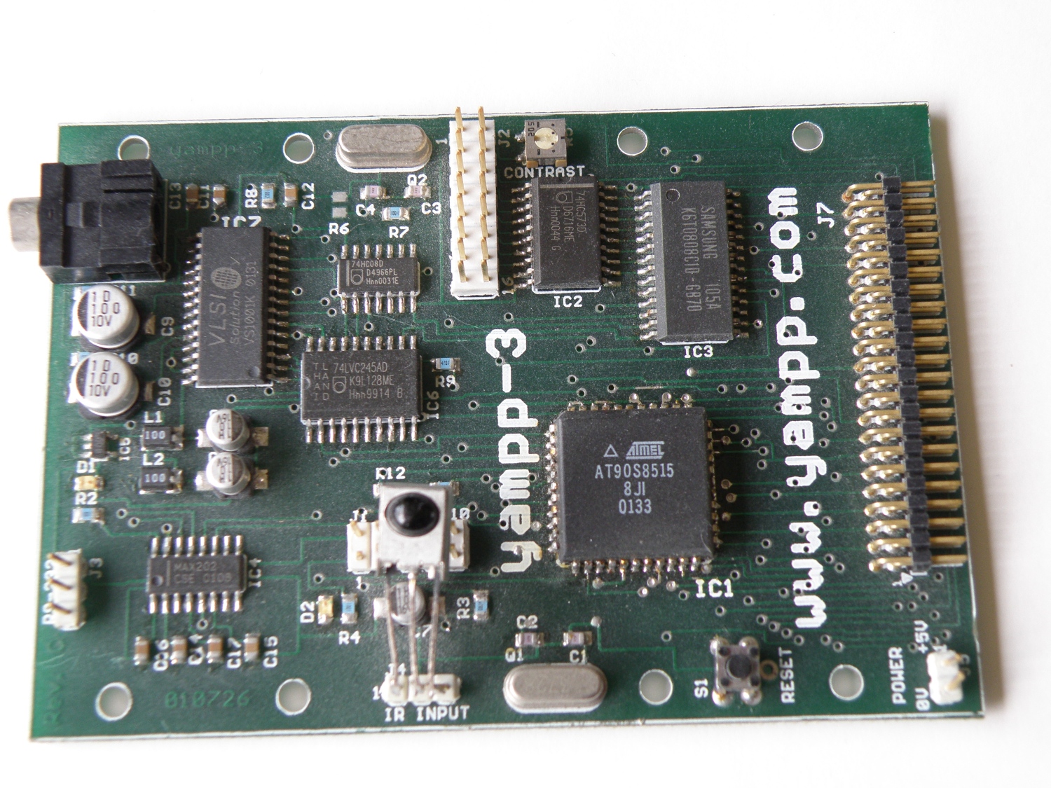
And the prototype, ram, rom, cpu all separated in dip package. The project never was finished, hard to realize with these components.
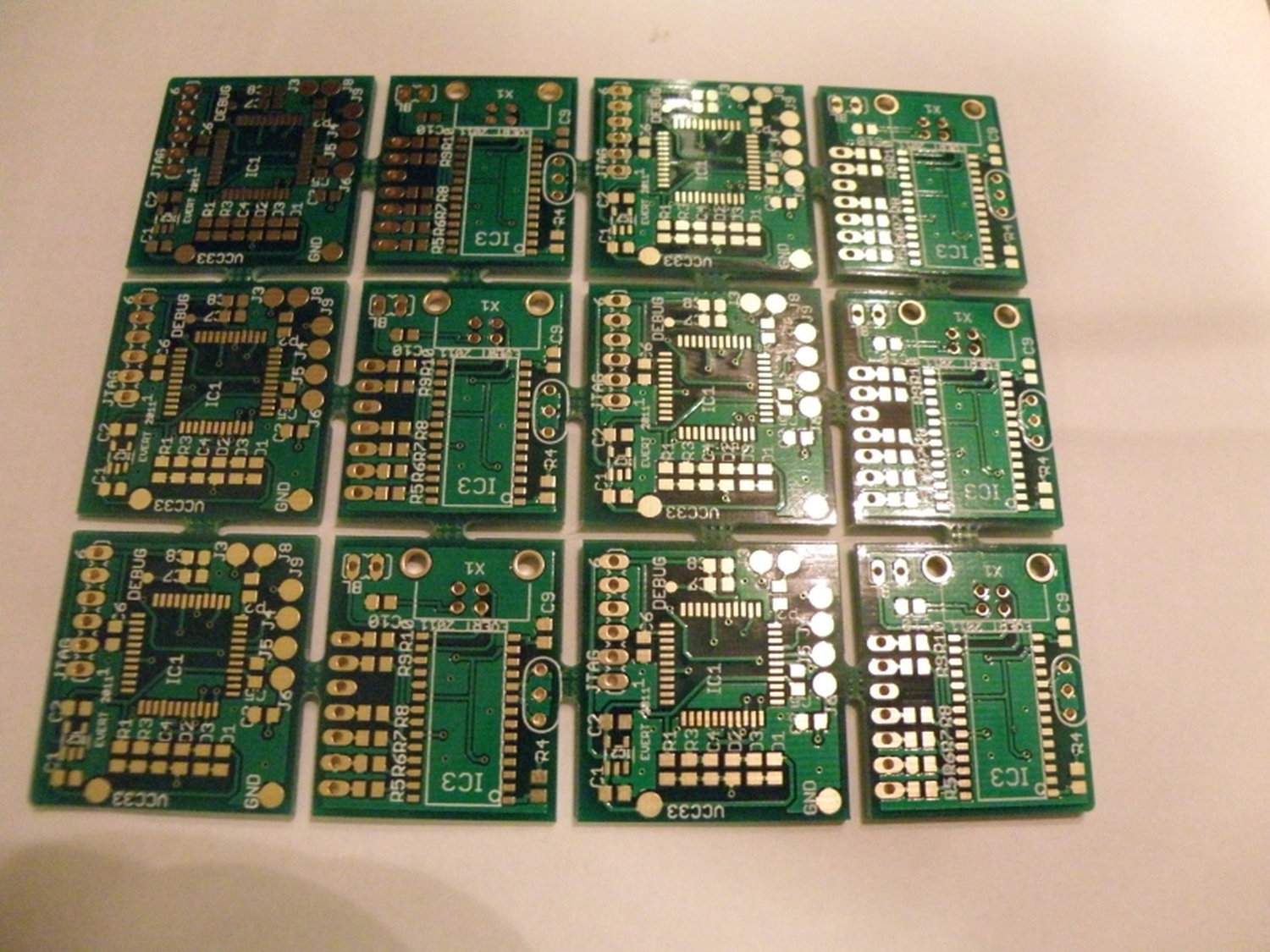
And the back with a lot of roadrunner wire again. Realizing this compact print on a regular 2 or 4 layer pcbs is hard to do, but with the roadrunner wire you can make as much “layers” as you like.
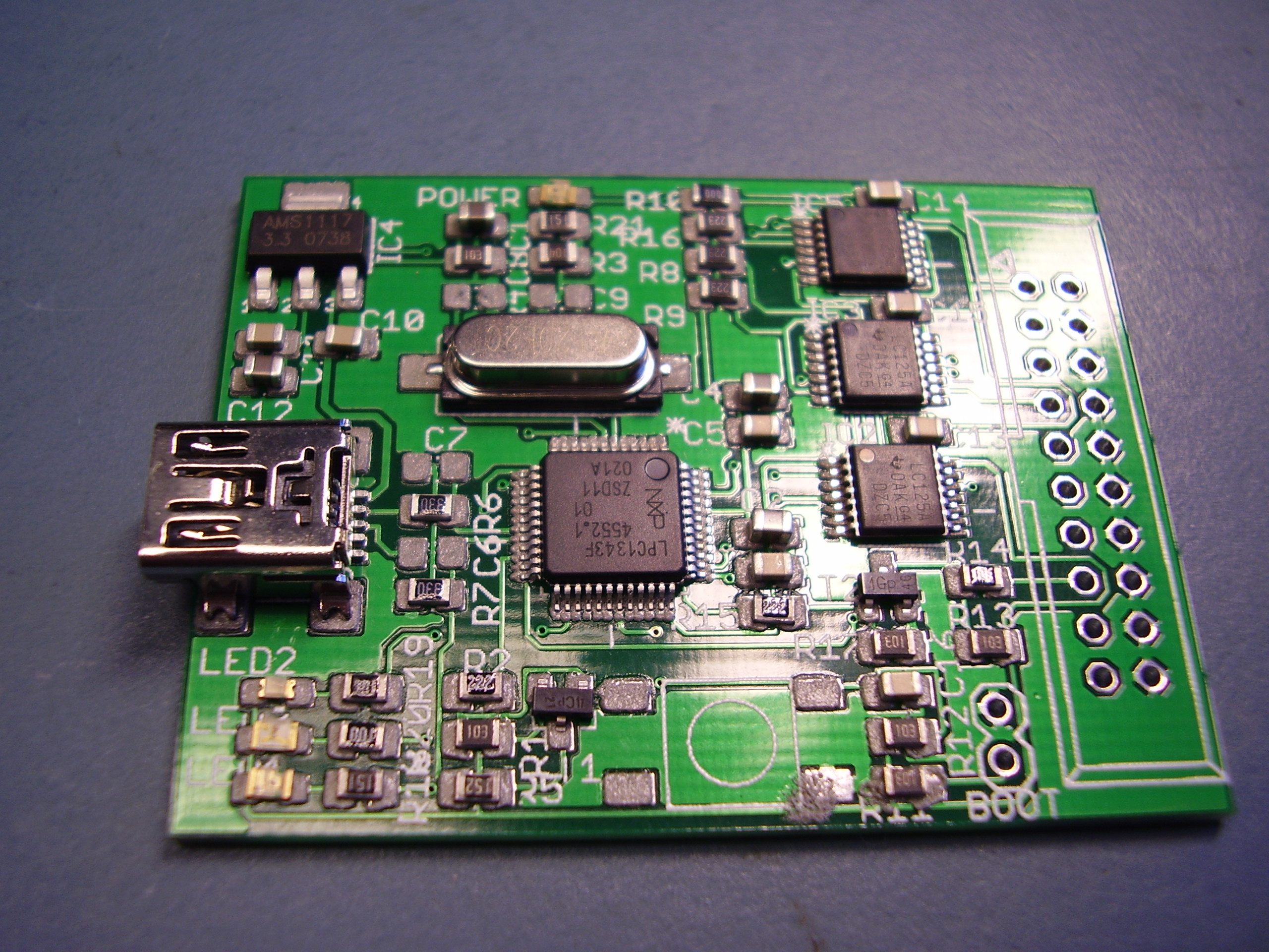
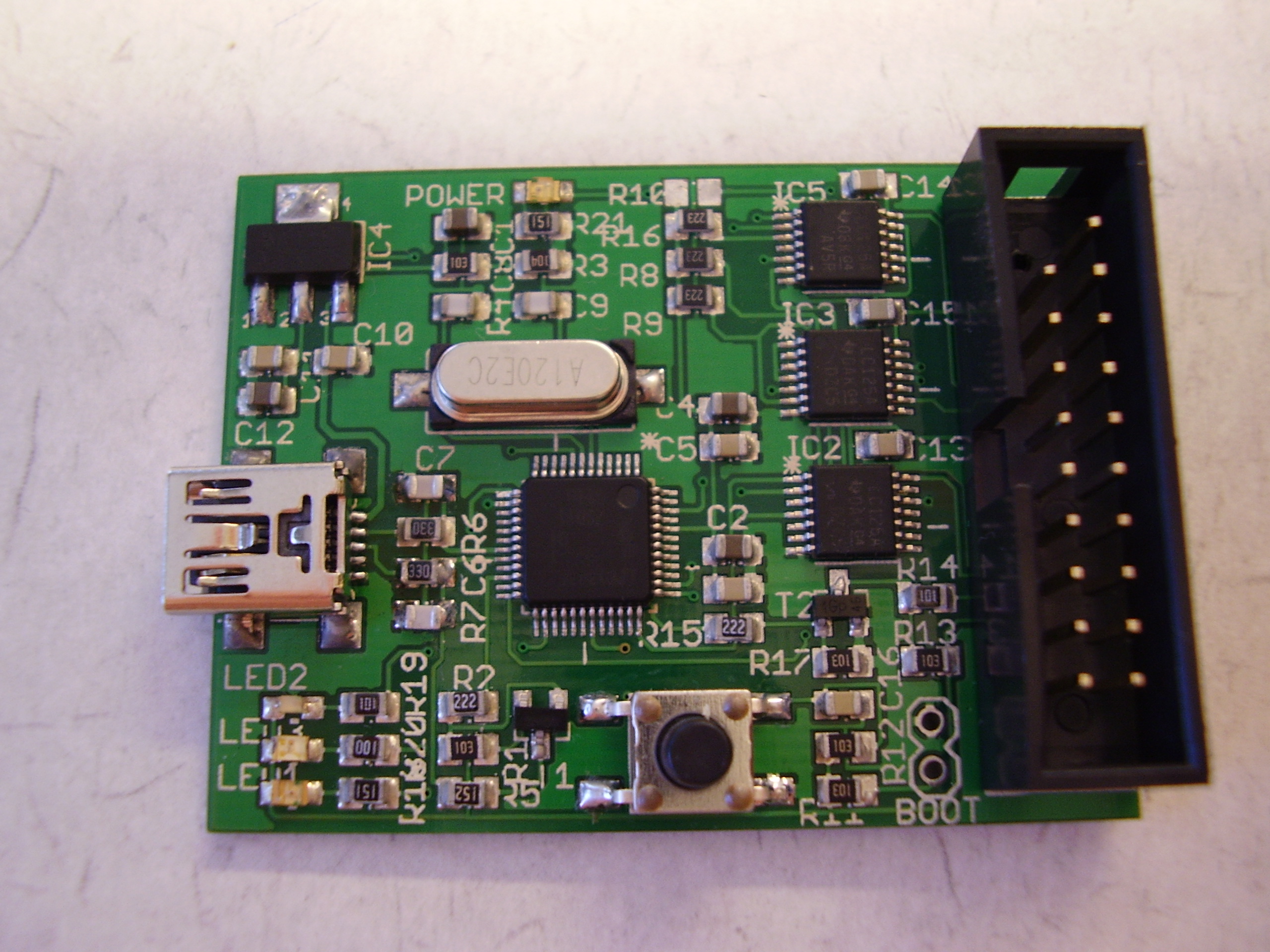
The rf board with tx and rx module. You can buy these modules now for a couple of dollars, but then they cost €75 for a set rx/tx.