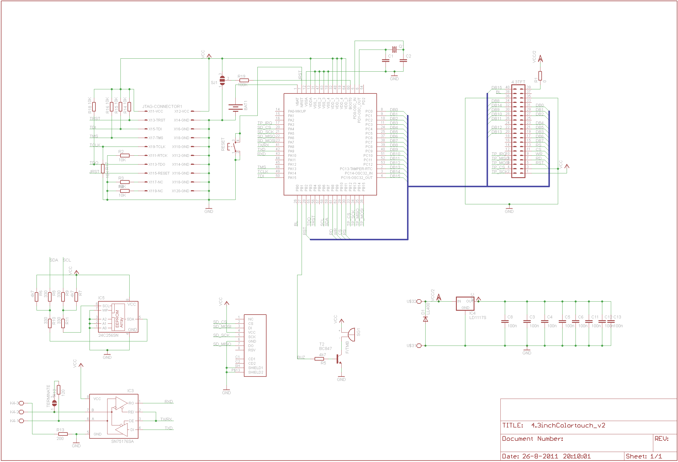
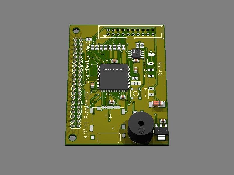
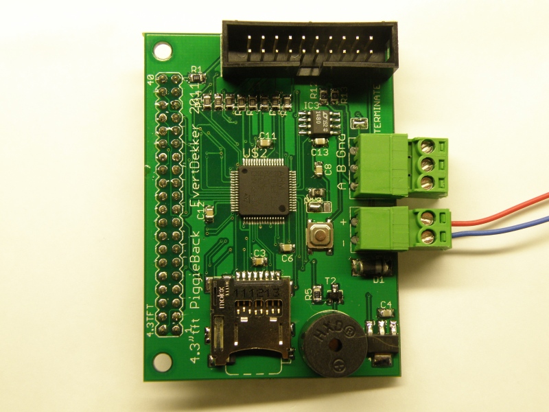
Bedroom blinds controller
This device will control the blinds in the bedroom and is controlled by the Joshua bus
It will also takes care of the led lighting in the closet.
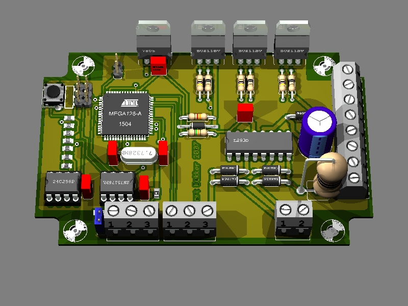
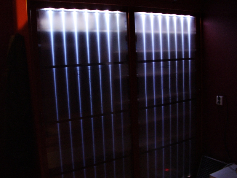
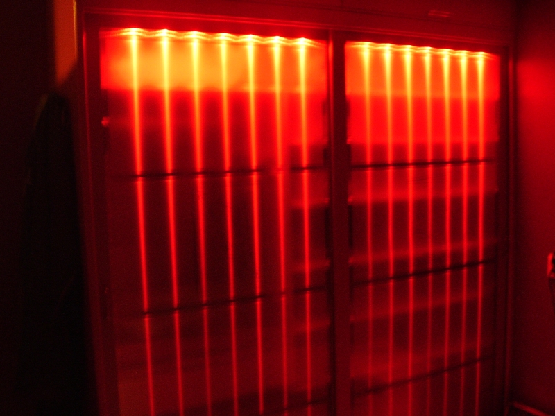
Led lightning in the sliding door white or red for special mood mode.

This device will control the blinds in the bedroom and is controlled by the Joshua bus
It will also takes care of the led lighting in the closet.
Led lightning in the sliding door white or red for special mood mode.
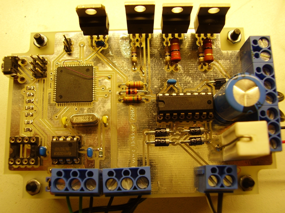
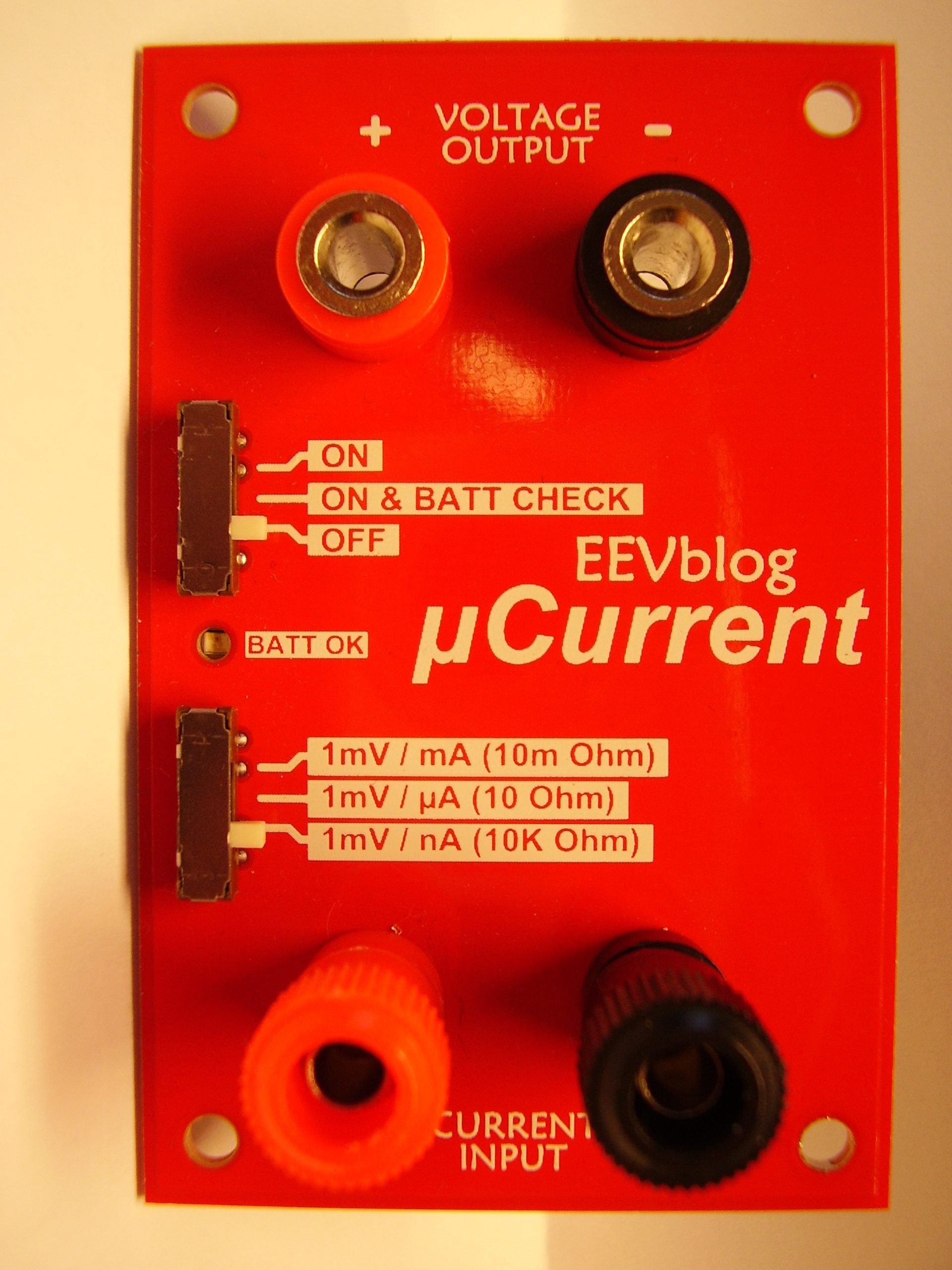
For a project at work I needed to measure precise the power consumption of a watch that I was developing. The power consumption was something like 17µA when running and 1.5µA when standby.
Normal multi meters have what the call “burden voltage”. This is the voltage that the internal current shunt resistor drops as you pass your circuit current through it and can have an big influence on the measuring.
To avoid this I want Dave Jones from EEVblog his µCurrent meter, but unfortunately it’s was sold out and not produced anymore.
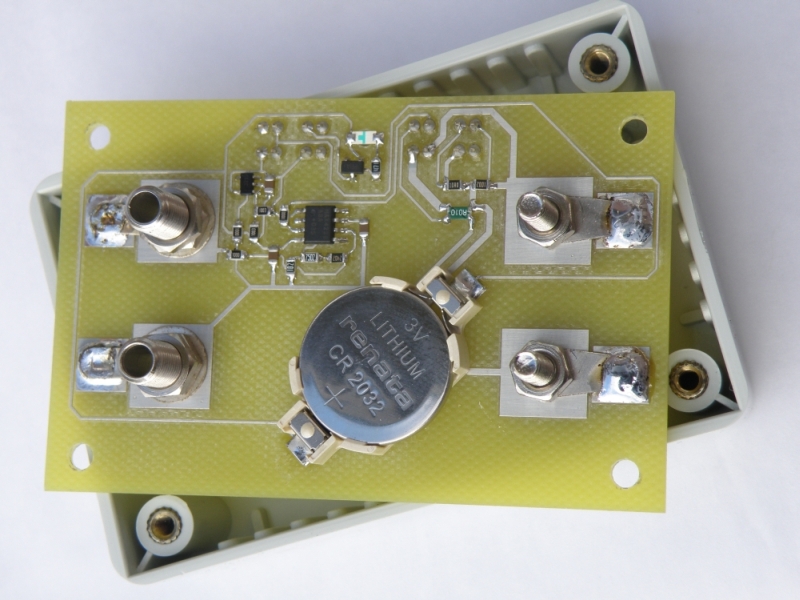
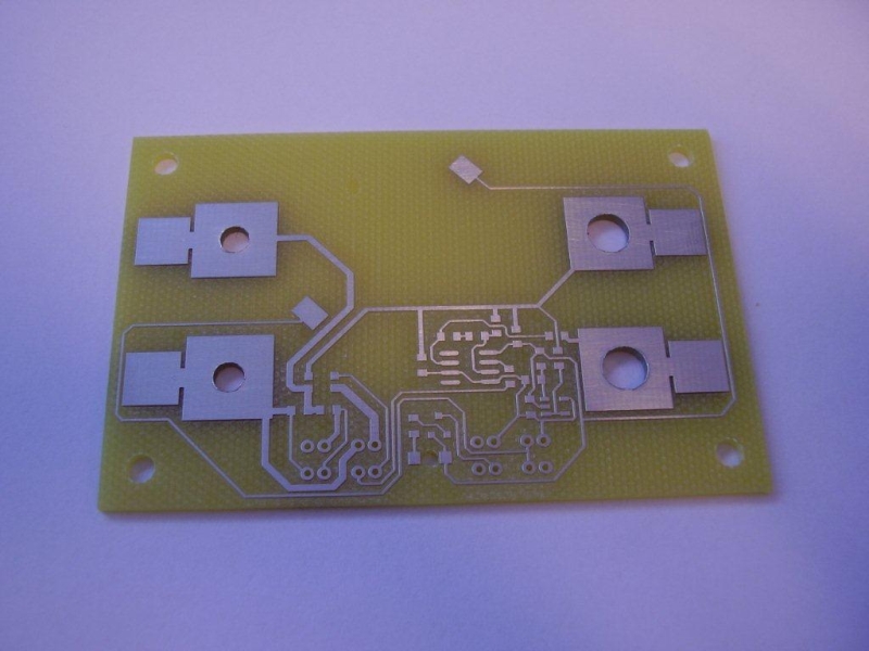
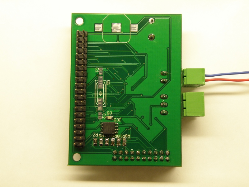
Time to build one myself. Dave was so kind to share the schematic and pcb design, makes it all a lot easier.
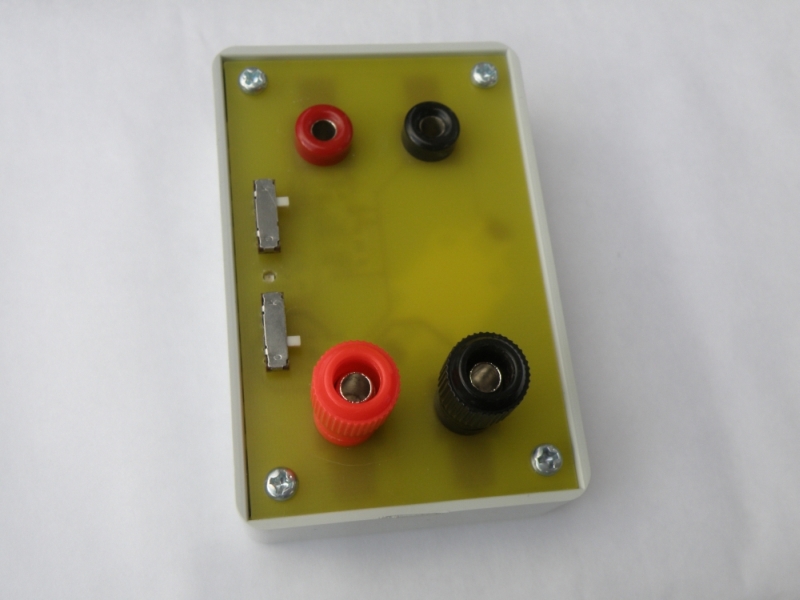
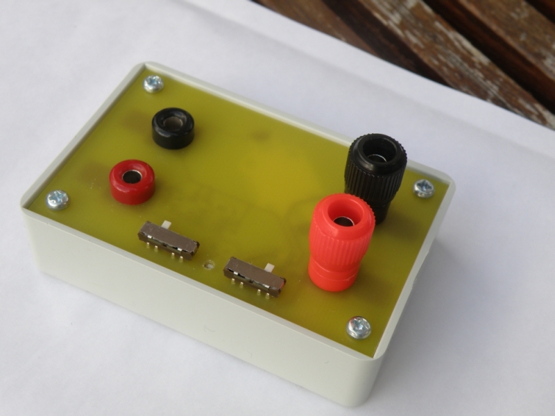
I made the first pcb for myself on the milling machine at work. Had to make some minor changes so that the pcb fits in enclosures that you can buy easy here in the the Netherlands, same for the the binding post.
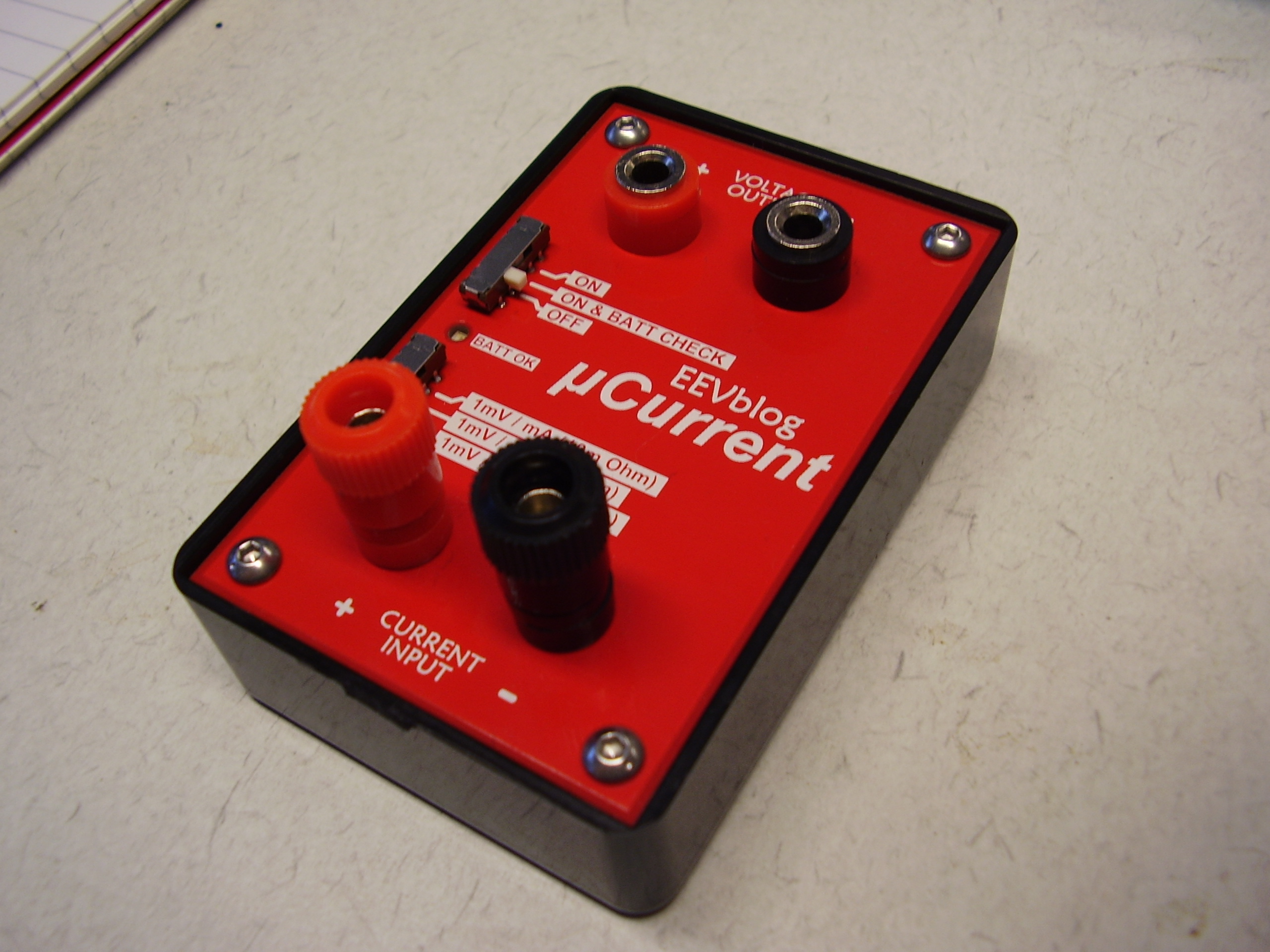
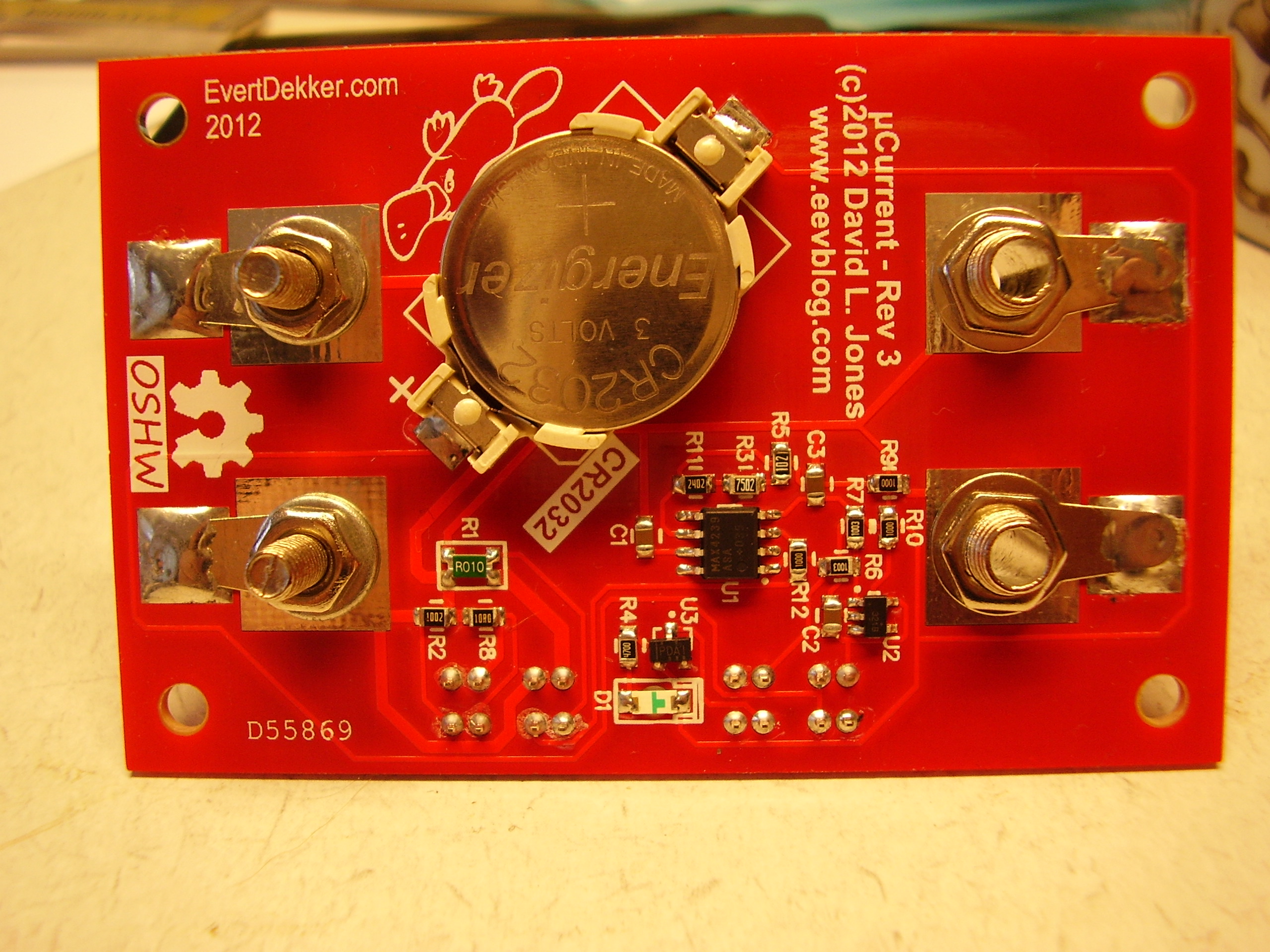
Friends and colleagues liked it that much that the also want one. Time to order some pcb’s in China, red ones to make them as beautifully as the original from Dave.
I’m very happy with this meter, is does what it needs to do. Compared with our old Goerz analog meter and it’s very accurate.
Still have some kit’s leftover, if your interested to build one yourself mail me.

Not a design from me, but a kit that I bought on the internet. Looked fun to me to build one, but you can forget the “fun” word very fast. What a hell of a job to soldering all the leds to the wires.
According the manual it was for an experience solderer 3 hours work. I can say I’m very experience, but it took me 9 hours.
Straighten all the wires was already a lot of work, after that you need to solder 5x5x5x4=500 pins from the leds to the wires.
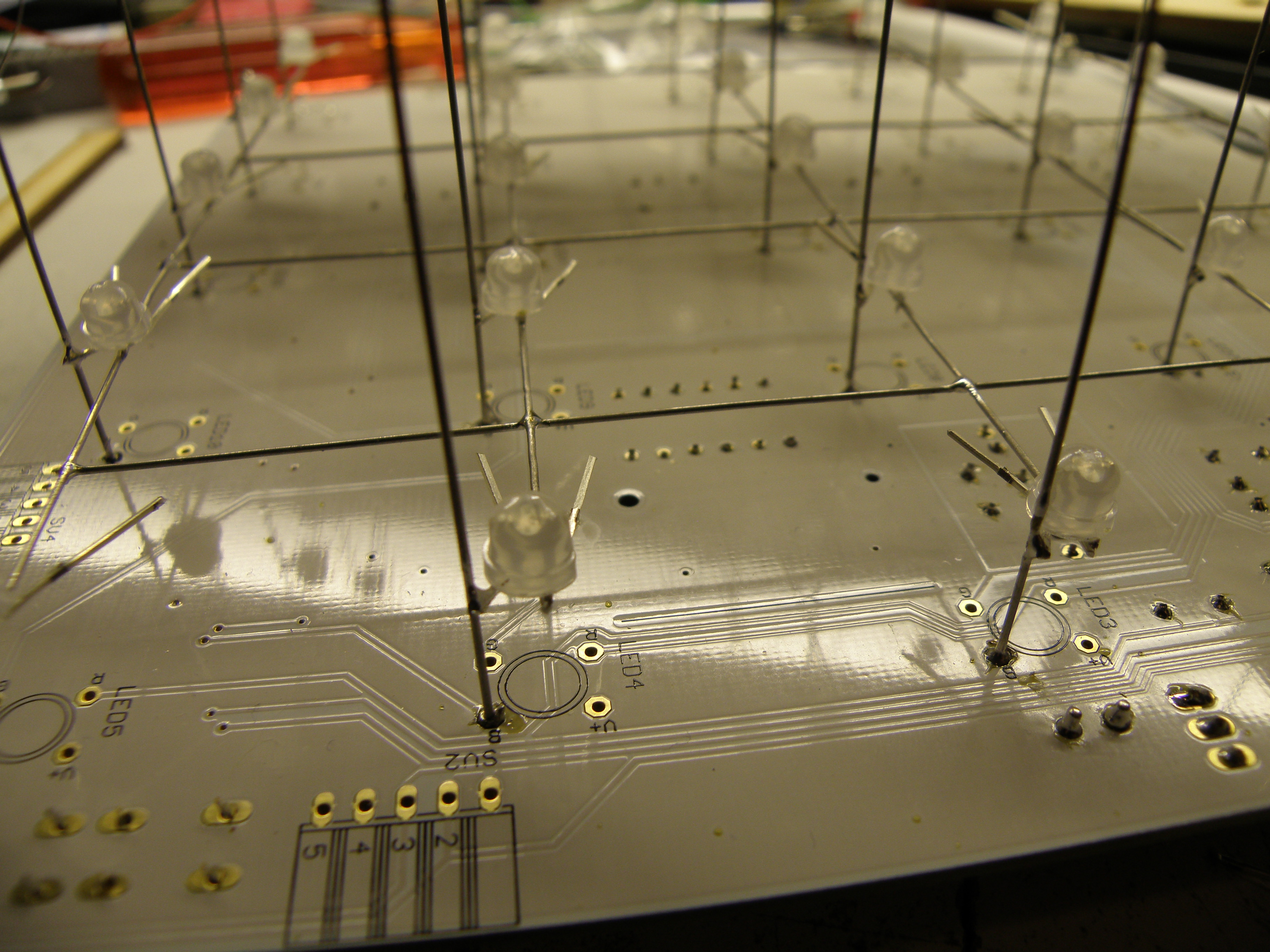
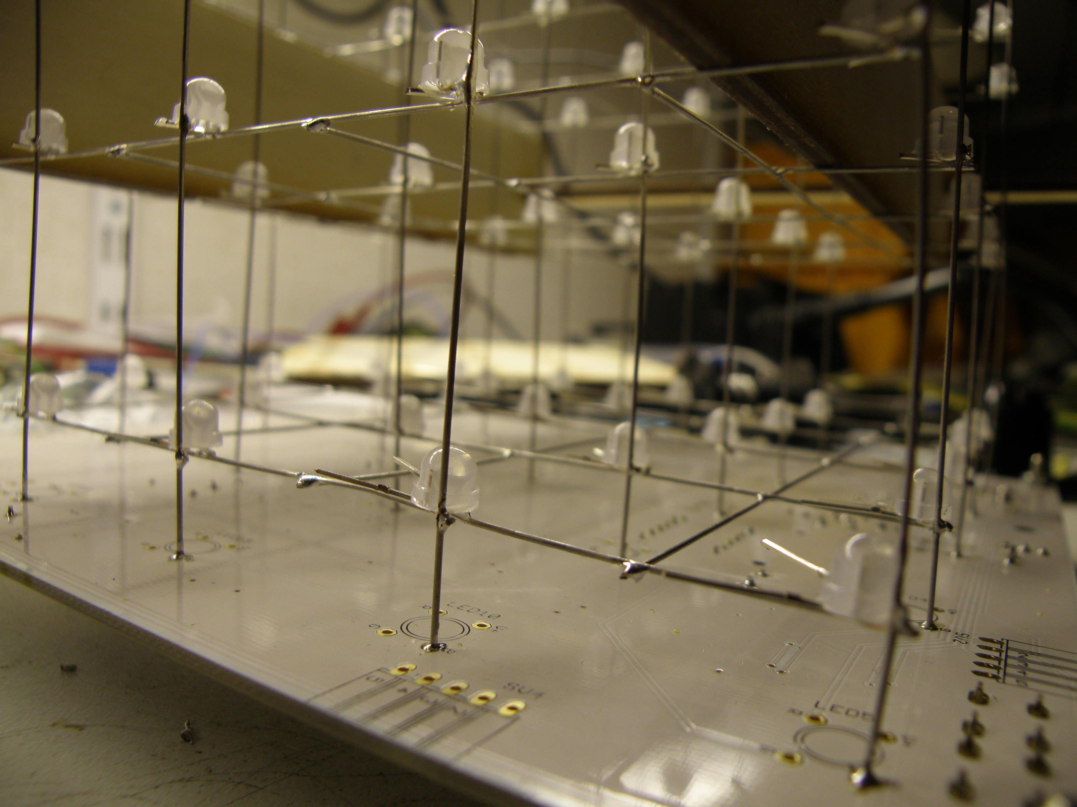
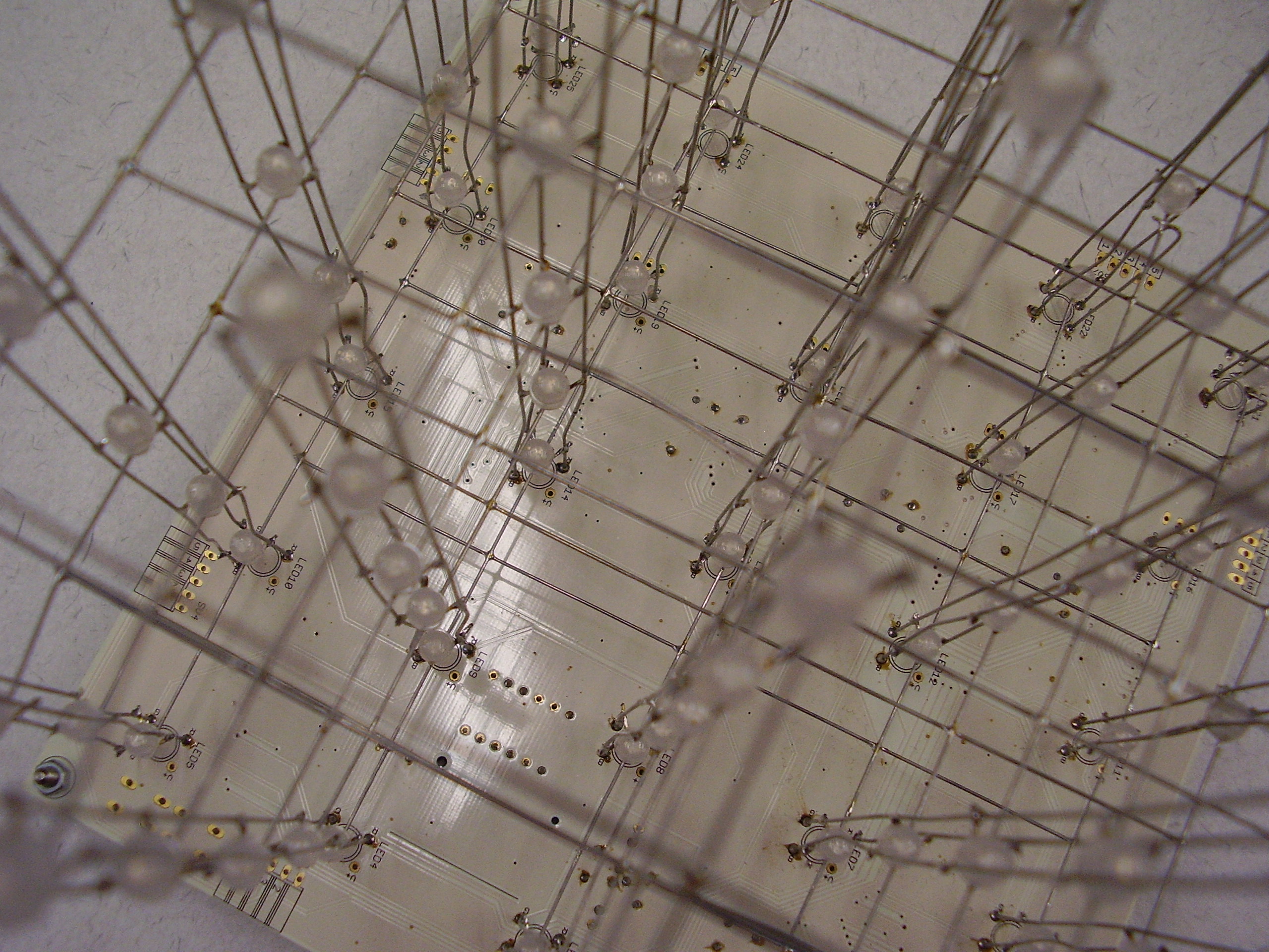
The first step was making the layers. For this they provided a die where you put the leds upside down in and then solder the common frame to all the leds in a matrix.
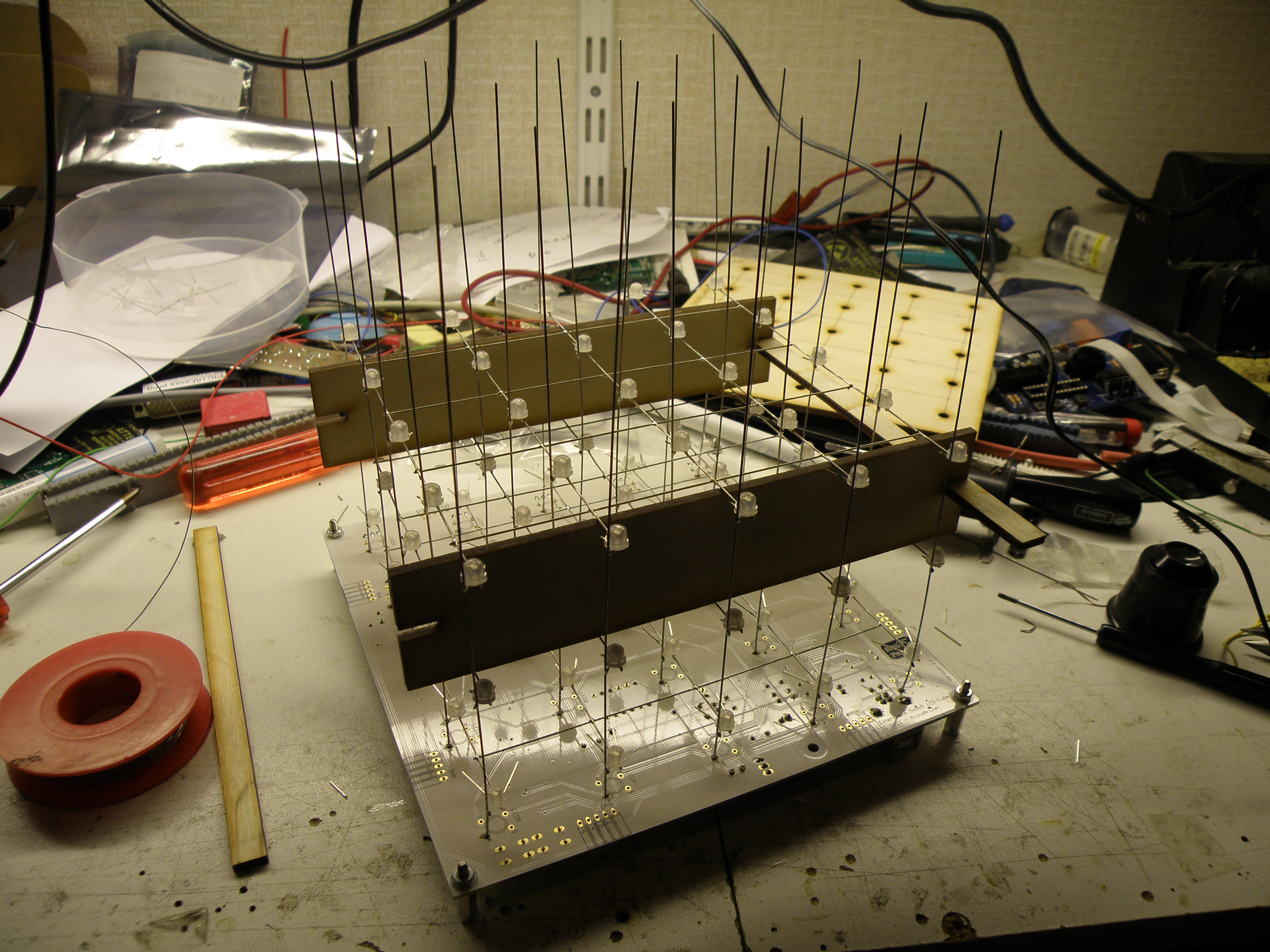
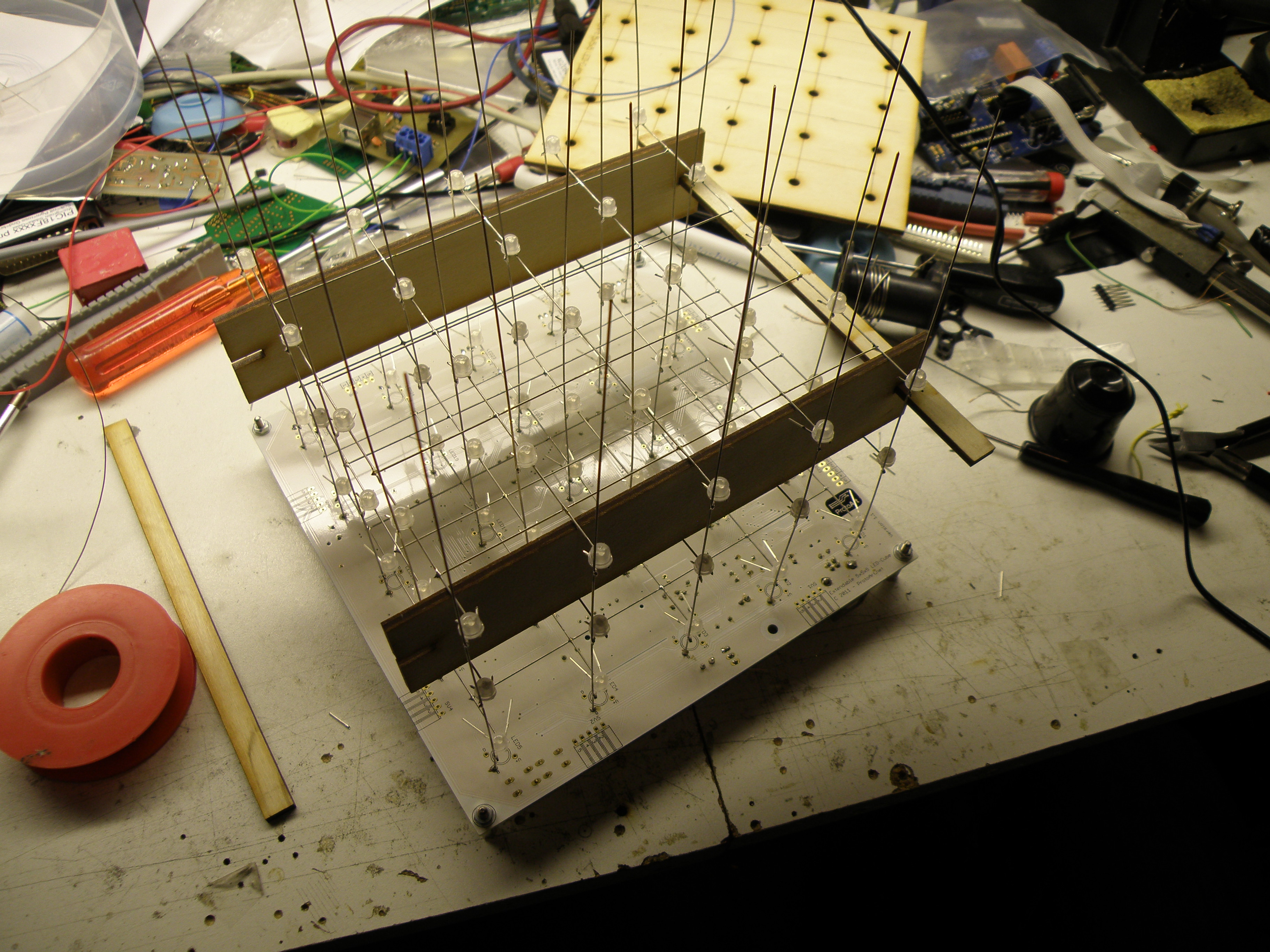
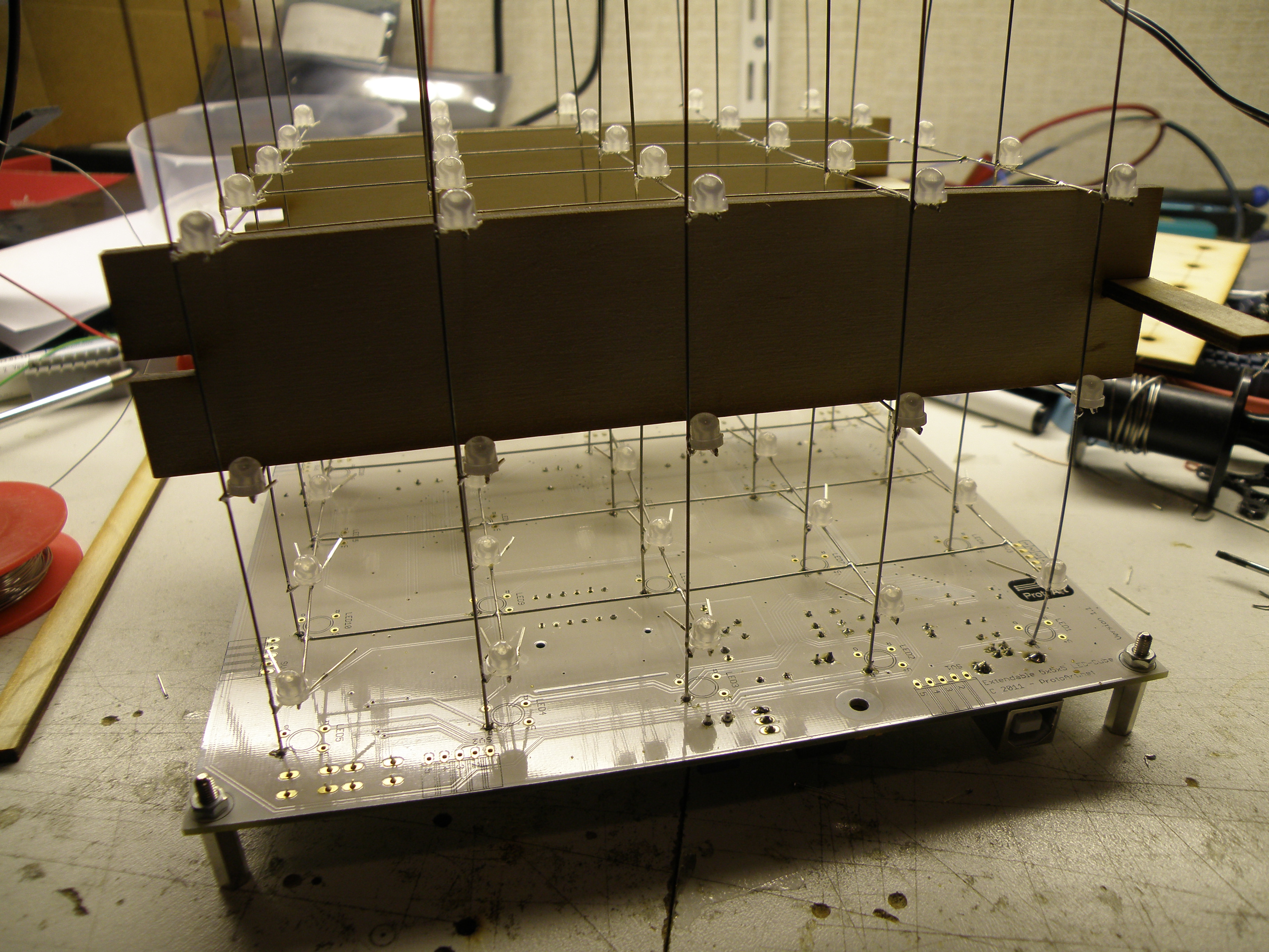
In the second step you needed to solder the vertical wires on the pcb and lower the layers from step 1 over it, holding it at the correct distance with the provided spacer and soldering the RGB pins from the leds to the wires. Repeat this for the other 4 layers.
The problem with this was if you didn’t bend the led pins precise in step one the led pin was not close enough to the vertical wire what made it difficult to soldering it. Bending the led pins a bit was not difficult for the leds on the edge, but the leds in the middle was hard to reach.
Finale finished with the soldering work and after uploading the test program to it…. 4 leds dead, and 3 not at the edge but in the middle.
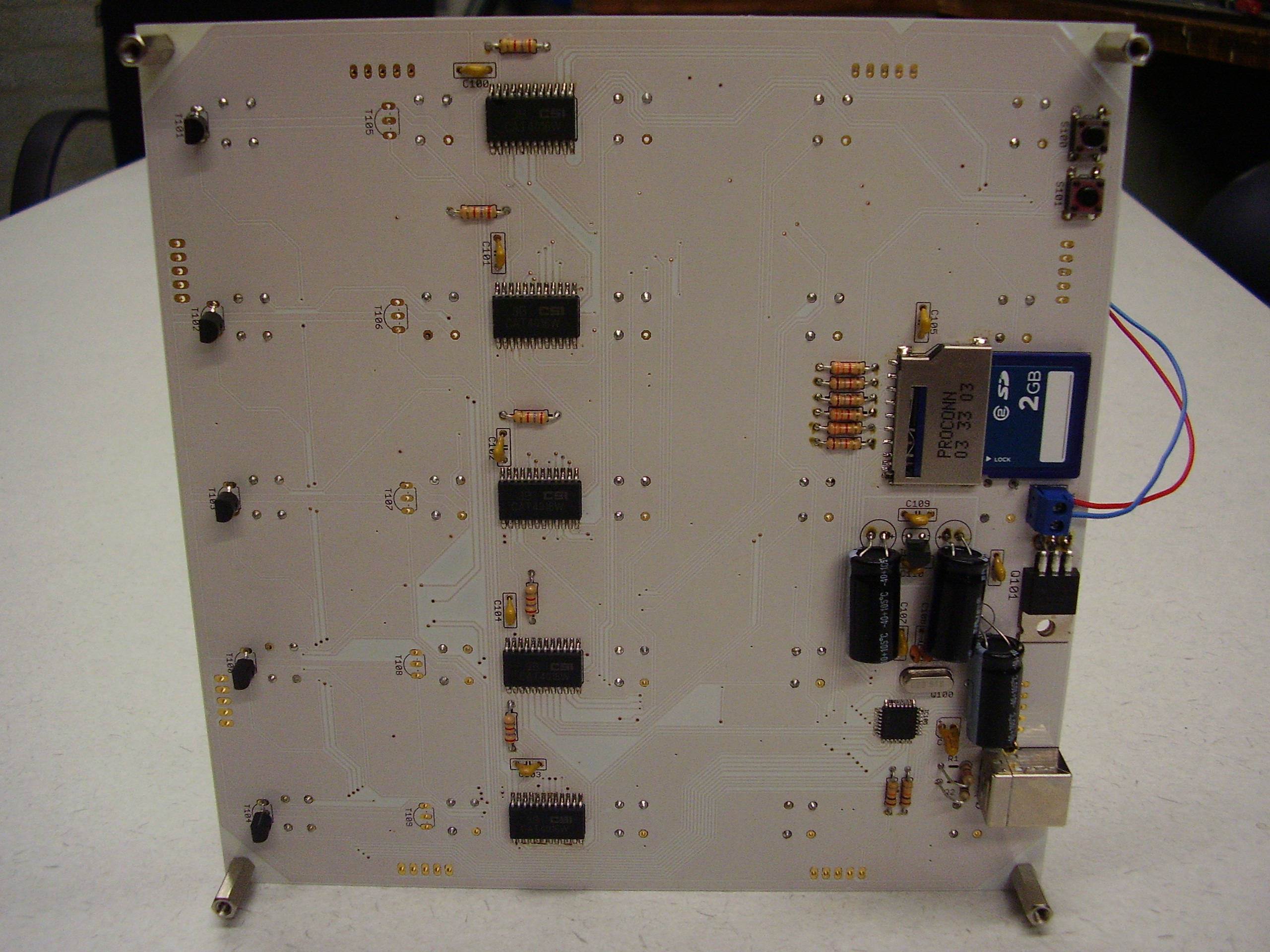
Very hard to get to the leds and replace them. During testing I blew up 1 of the drivers (CAT4016W) due difference in ground potential from my soldering iron. After replacing the driver everything was working fine finally.
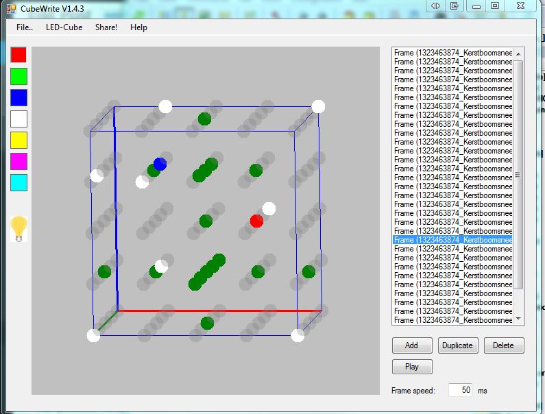
With the provide PC tool you can make your own sequence and upload it to the sd card in the cube.
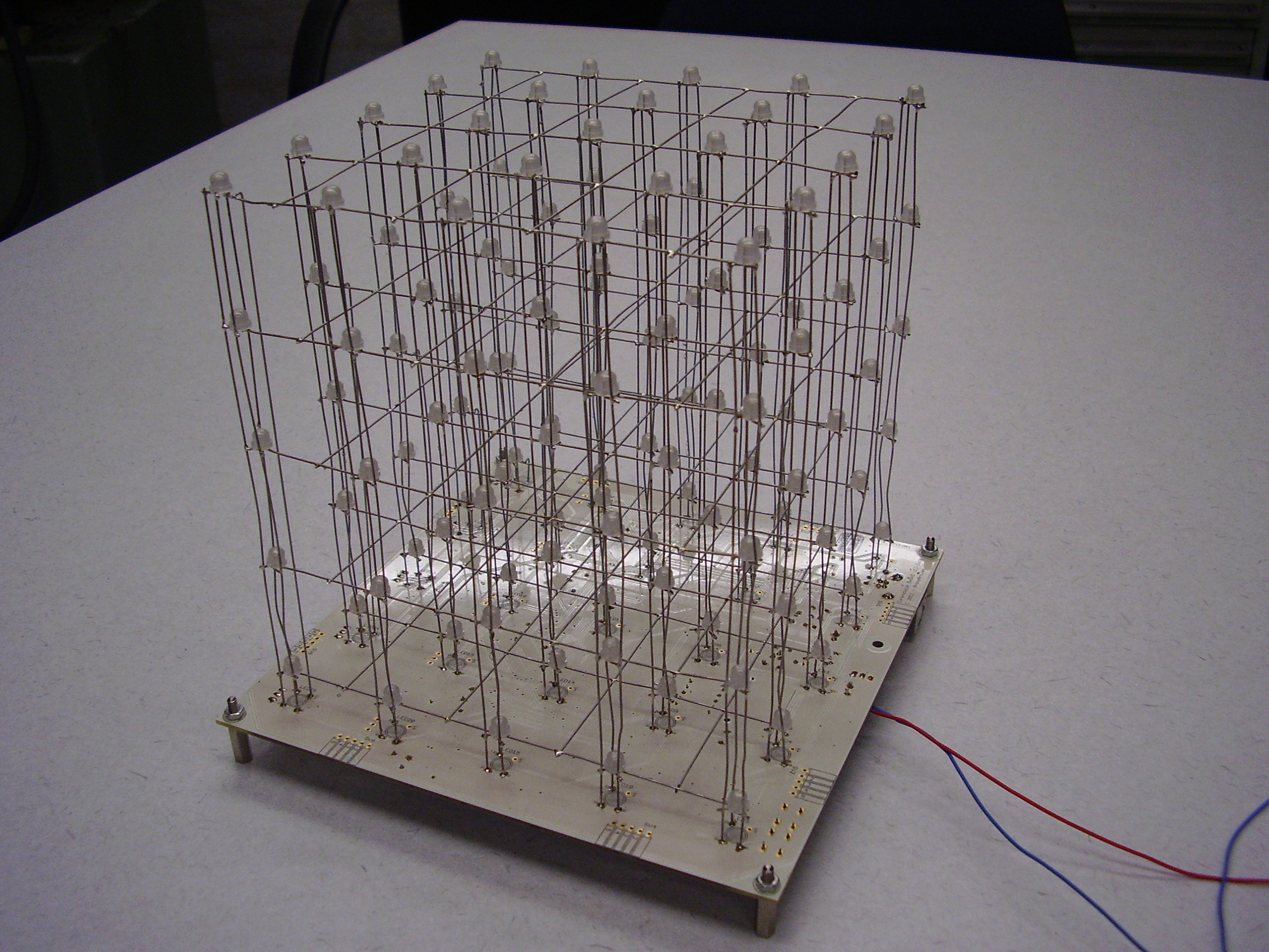
But, not all the troubles where over now. I did bring it to my work to show it to my colleagues and one of them dropped the cube on the floor with the result is was completely bend. Did bend it a bit back but was to anxiously that it could brake. See the result in the Finished picture, this is the result after the drop, befor it was nice straight.
After this disaster the next one was there, somebody used my power supply for other purposes and set it to 12V. I didn’t checked it and switch it on with the result that all the drivers where fried. Back to the soldering iron again to replace them all.
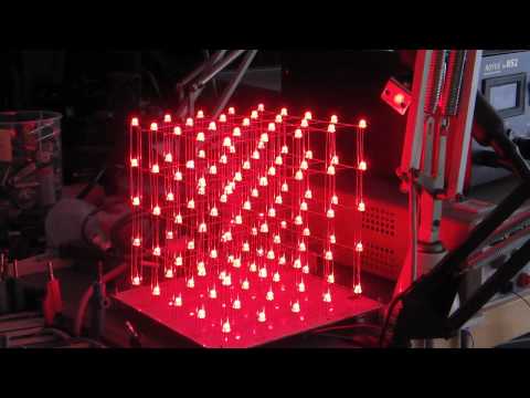
Small impression of making the cube and the result.
The cube in action. Due the multiplexing of the layers and the camera shutter it flickers a bit, but in real it doesn’t.
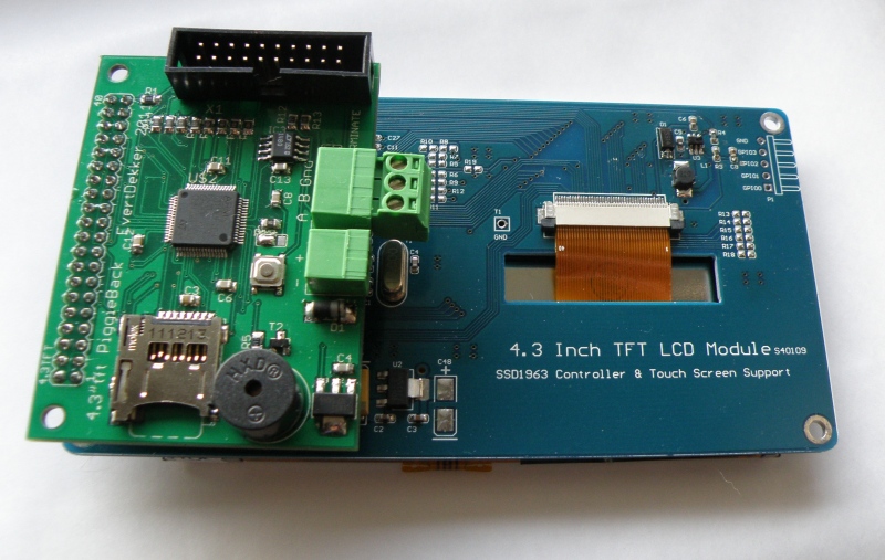
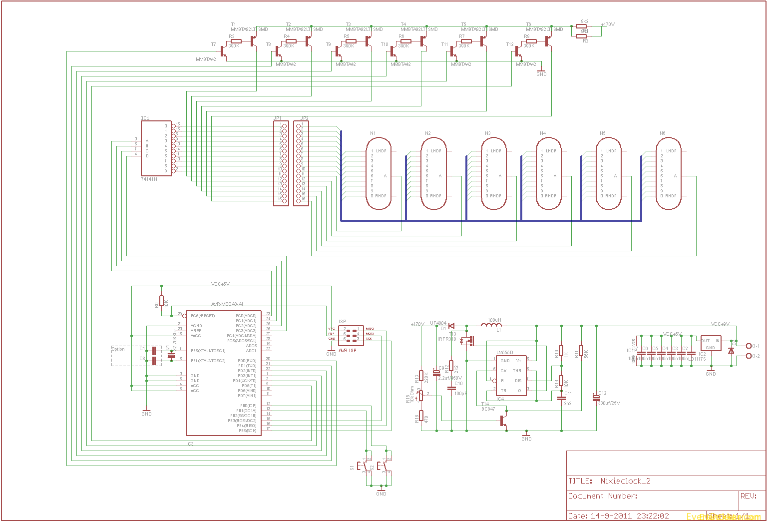
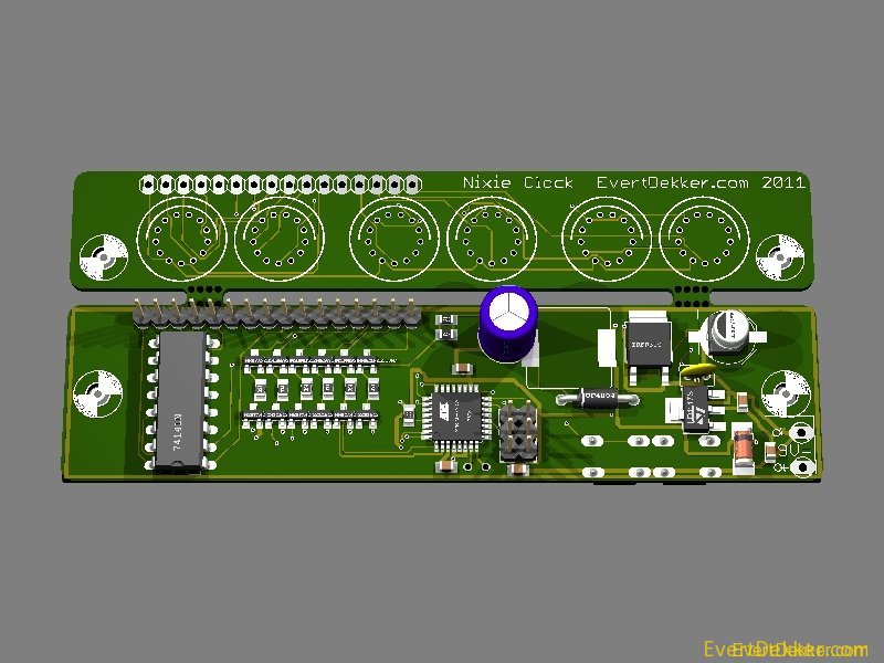
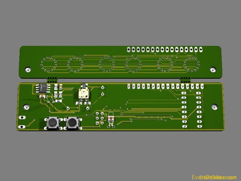
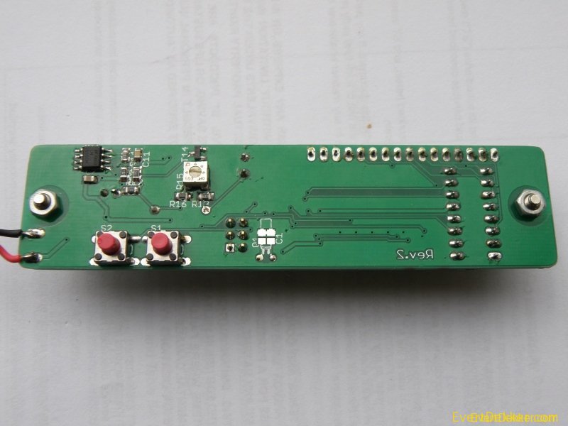
My second nixie clock design.
This clock is compared with my other Nixie clock much simpler, it uses less components and the code is kept simple and short.
The segments are multiplexed to increase lifetime of the tubes and simplify the 170V power supply.
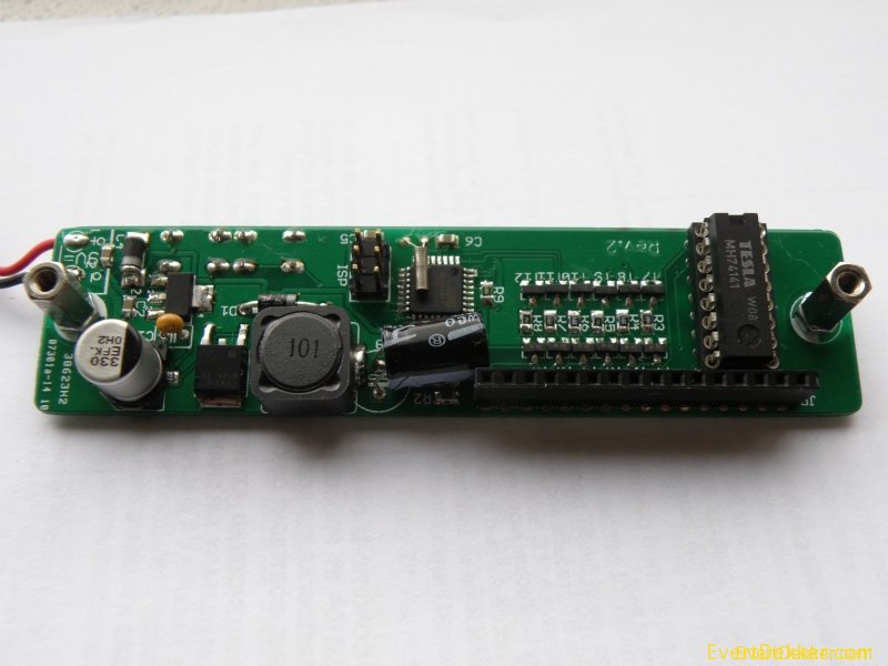
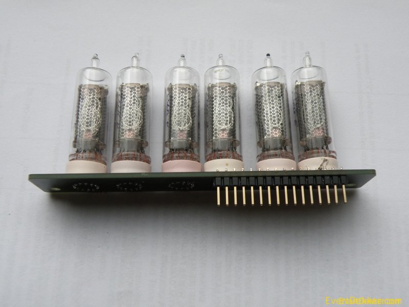
Due the separate tube pcb it’s possible to use it with other tube’s. I have used IN-16 tubes for this clock, bought them on ebay.
To-do: Wooden enclosure with aluminum top and bottom.
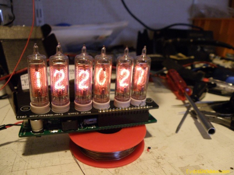
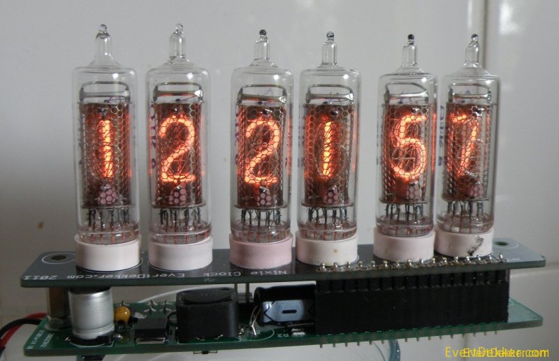
The clock in action.
Multiplexing in action, shot with 1000fps camera
'============================================================================

'=  Simple IN-16 nixie tube clock with multiplexed segments, low part count =
'=             Shortest Nixie Bascom code available on the net              =
'=                                                                          =
'=                    Copyright Evertdekker.com 2011                        =
'=                    Code Created with Bascom 2.0.7.1                      =
'============================================================================

$regfile = "M88pdef.dat"
$crystal = 1000000                                          'Internal 8mhz div/8
$hwstack = 32
$swstack = 64
$framesize = 16

Config Clock = Soft                                         'Use the softclock, 32.768KHz crystal connected to tosc1/2
Config Date = Dmy , Separator = -
Enable Interrupts
Date$ = "15-03-11"
Time$ = "12:15:45"

'== Setup hardware ==
Digit Alias Portc
Config Digit = Output                                       'Set up portc as output for the digit
Ddrd = &B00111111                                           'Setup portd as output for the segment and keep bit6&7 free for other use
Button_hr Alias Pinb.0
Button_min Alias Pinb.1
Config Button_hr = Input
Config Button_min = Input                                   'Set buttons as input
Set Portb.0
Set Portb.1                                                 'Switch on the pullup for the buttons

Dim Multiplex As Byte
Multiplex = 1                                               'Multiplexer starts with 1

Do

Select Case Multiplex
 Case 1 : Digit = _sec Mod 10                               'Seconds
 Case 2 : Digit = _sec / 10                                 'Seconds tens
 Case 4 : Digit = _min Mod 10                               'Minute
 Case 8 : Digit = _min / 10                                 'Minute tens
 Case 16 : Digit = _hour Mod 10                             'Hour
 Case 32 : Digit = _hour / 10                               'Hour tens
End Select

Portd = &B11000000 Or Multiplex                             'Switch on one tube
Waitms 2                                                    'Some delay to slow down the multiplexer

If Multiplex < 32 Then                                      'Shift the multiplexer one bit to the left until all 6 segments are done
 Shift Multiplex , Left , 1
Else
 Multiplex = 1                                              'Start over again at segment 1
End If

Debounce Button_min , 0 , Setminute , Sub                   'One of the buttons pressed, jump to the sub to change the time
Debounce Button_hr , 0 , Sethour , Sub

Loop
End

'=== Subs ===
Setminute:
 Incr _min
 If _min > 59 Then _min = 0
Return

Sethour:
 Incr _hour
 If _hour > 23 Then _hour = 0
Return