EvertDekker.com

Evert Dekker
  • Home

Search

Recent Posts

  • Doublelock Sensor
  • Nixie Clock #3
  • Iot house exhaust air systems controller
  • PZEM-016 Energy Monitor
  • Tweaknews OpenVpn

Projects

  • expandCode Vault (14)
    • expandArm Cortex (1)
    • expandBascom (10)
    • expandMini2440 (1)
    • expandVB 5..2010 (2)
  • collapseElectronic Projects (65)
    • expandEsp32 (4)
    • expandEsp8266 (13)
    • expandJoshua Domotica (25)
    • expandOldies (3)
    • expandRc Car Projects (4)
    • expandVarious Projects (16)
  • expandSoftware (9)
    • expandArduino (1)
    • expandJoshua (1)
    • expandNokia N900 (1)
    • expandPC (6)
  • expandVarious projects (3)

Popular Posts

  • Iot SensorV2 with battery onboard
  • PZEM-016 Energy Monitor
  • Esp32s Altium library
  • Esp-01 Programmer Mod
  • Nixie Clock

Archives

Menu

  • My Tube
  • Contact me
  • Privacy Policy

Counters

  • 1107681Total reads:
  • 163Reads today:
  • 154Reads yesterday:
  • 1729Reads last week:
  • 6236Reads per month:
  • 325907Total visitors:
  • 126Visitors today:
  • 133Visitors yesterday:
  • 1204Visitors last week:
  • 3973Visitors per month:
  • 154Visitors per day:
  • 0Visitors currently online:
  • September 9, 2007Counter starts on:

My Github Projects

  • Blinkled
  • DHT22-Esp8266-HW-Test
  • DHT22-ESP8266-Temperature-Node
  • ESP8285-Sonoff-Slampher-V2
  • IotPirLight

Meta

  • Log in
  • Entries feed
  • Comments feed
  • WordPress.org

Esp-01 Programmer Mod

May24
by Evert on May 24, 2018
Posted In: Esp8266
Share this cool post on social media
  • 4
  •  
  •  
  •  
  •  
  •  
  •  
  •  
  •  
  •  
  •  
  •  
  •  
  •  
    4
    Shares

For a small project of my there was needed a programmer for the Esp-01 wifi module to program the module. It’s not really a programmer, but more an usb to serial convertor.
Simple search on Aliexpress gave a nice looking programmer that you can stick in your pc and voila Esp-01 can be programmed, can be bought for $0.78 including shipping.

Bummer, when it arrived and want to use it to program the Esp-01 module it wasn’t possible to get it working with the Arduino ide. The ide was constant coming with the error espcomm sync failed and other com port related errors.
After a quick google search it was clear, the bought Esp-01 programmer works fine out of the box when you use the Esp-01 with the AT commands, but for using it with the Arduino Ide the Esp-01 module had to be set first in programming mode by connection GPIO-0 to ground and reset the module to bring it in flash uart download mode.
Most of the solutions found on the net uses 1 or 2 buttons to get this accomplished, but I wanted automatic programming mode just like the NodeMCU does. Just press upload in the Arduino ide and go….

The programmer uses the same usb to serial convertor (CH340G) as used in the NodeMCU so it should be possible to use the same schematic. The Arduino Ide already supports the NodeMCU so no need to change drivers, board.txt or platform.txt files.
The part that’s responsible for pulling GPIO-0 low and resetting the Esp-8266 is only two general purpose npn transitors and 2 resistors.

Schematic

So I added 2x BC547 (or use any other general purpose transistor) and 12K resistors to the bottom of the programmer board. It’s not my best soldering work, but it will do the job.

Bottom View

Soldered 2 wires to pin 13 and 14 of the CH340G and connected them to the transistors on the other side.
You can fix everything with some hotglue if you want.

Top view

Change in the Arduino ide the setting Tools , Reset Methode to NodeMCU and you are ready to go.
Every time you press now upload the Esp-01 will be set in serial download mode and you can upload you fresh developed code.

Arduino Ide Setting


Happy programming.


1 Comment

Iot SensorV2 with battery onboard

May05
by Evert on May 5, 2018
Posted In: Esp8266
Share this cool post on social media
  • 4
  •  
  •  
  •  
  •  
  •  
  •  
  •  
  •  
  •  
  •  
  •  
  •  
  •  
    4
    Shares

Not a complete new design, but a redesign of my Iot Esp8266 sensor V2, the schematic is exact the same however this time with a on board 18650 3.7V Li-ion battery.

The Iot sensor node will measure temperature, humidity, atmospheric pressure and light. The light is measured with the TSL2561 and temperature, humidity, atmospheric pressure with the Bosch BME280.

In the previous design the battery was placed in a separate battery holder and the pcb was taped to the battery, not really the ideal solution.  So the idea was born to combine everything on 1 pcb.
The first idea was to place the battery beside the electronics, when this was finished I thought that can be smaller and made also a design where the pcb is on top of the battery. Still I couldn’t decide if I wanted the side or top version. Ok, lets combine both designs and we will see later what’s version is nicer.
Just as mentioned in then previous design, it’s very hard to solder the BM280. My opinion is that you only can solder it good if you use a stencil to apply the solder paste and place the pcb in the oven or use a hot air station.
For the battery clips I used the Keystone 16~19mm PC Battery clip.  In the datasheet they note that for an 18650 with build in protection circuit you need 48mm between the front solder pins, that will make it fit for battery’s of 68mm if you add the rest of the clip. However I don’t think this is correct, at least not in my case. 18650 battery with build in protection are 69,7 mm long, it will fit but it looks that it’s way to tight. For 18650 battery with flat head the clips are to far apart and won’t make contact. An 18650 with button head will fit perfect. If you want to make your own sensor node, keep in mind that there are a lot of different sizes 18650.
I’m using now the Sanyo NCR18650GA 3350mAh – 10A Button Top and that fits perfect, they are 66.7mm long (battery used on the photo’s is not the Sanyo).

Always nice to preview the design in Altium Always nice to preview the design in Altium
Pcb and stencil Pcb and stencil
All the components are placed All the components are placed
The version that sits on top of the battery The version that sits on top of the battery

Pcb slightly bend with this battery Pcb slightly bend with this battery
Battery next to electronics Battery next to electronics


You can find a test/demo Arduino program on my Github.


If you want to make your own, or use parts of the design here are  the Altium Designer 16 files:

Download Now!
753 Downloads


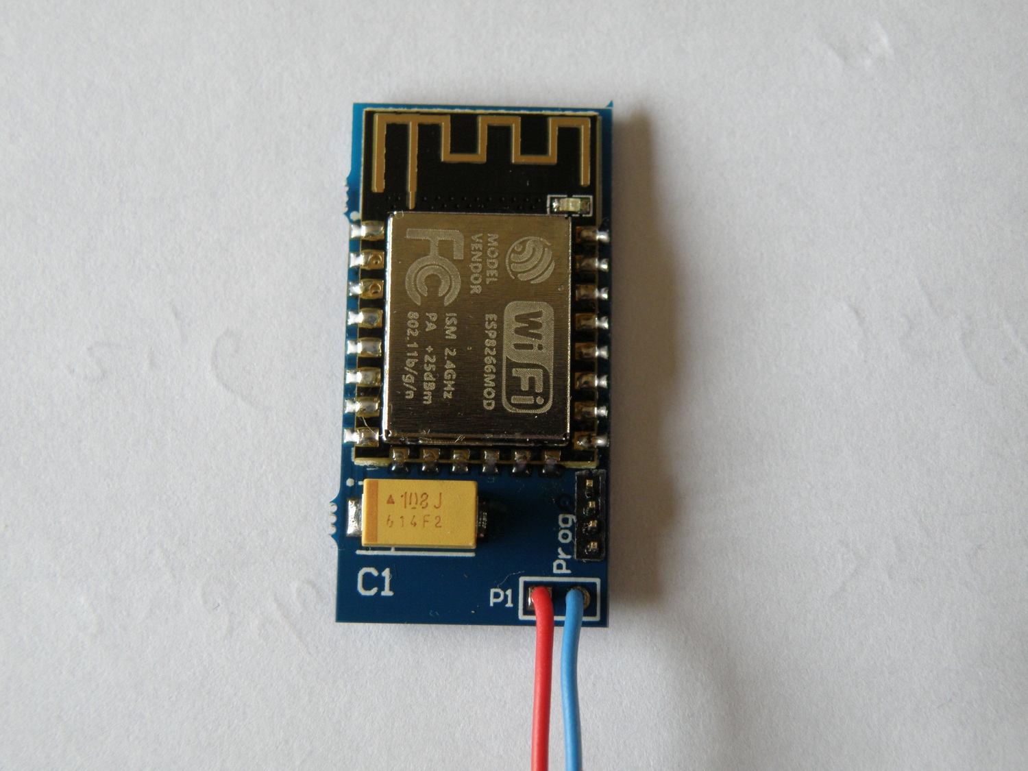
IoT Esp8266 BME280 sensor

Mar11
by Evert on March 11, 2018
Posted In: Esp8266
Share this cool post on social media
  • 4
  •  
  •  
  •  
  •  
  •  
  •  
  •  
  •  
  •  
  •  
  •  
  •  
  •  
    4
    Shares

Iot Esp8266 temperature, humidity, atmospheric pressure and light sensor.

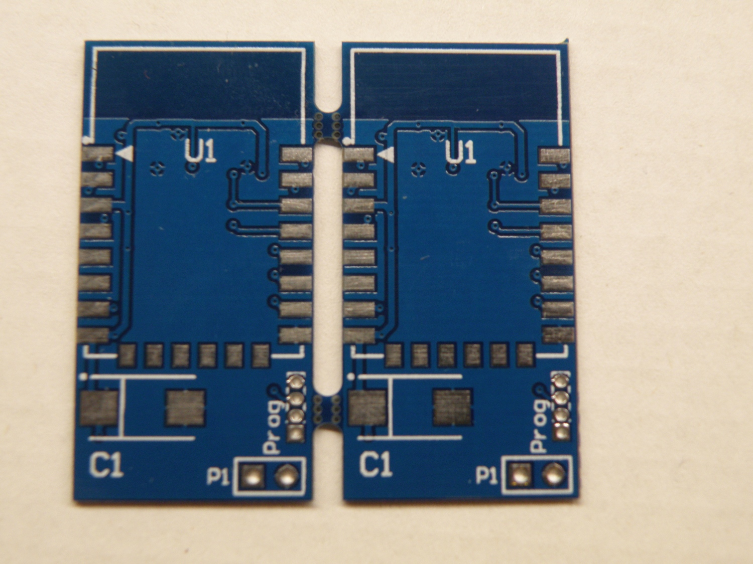
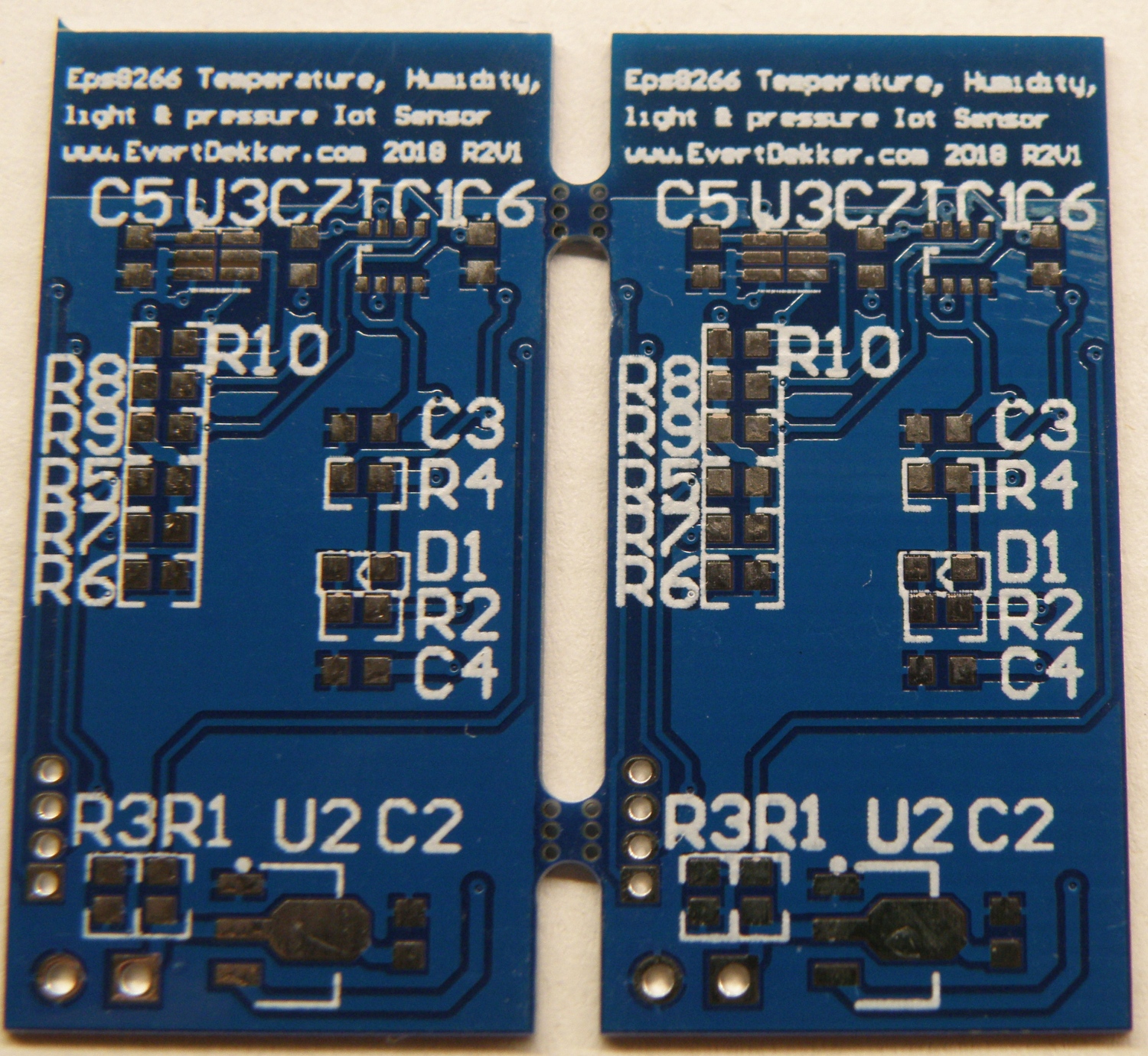
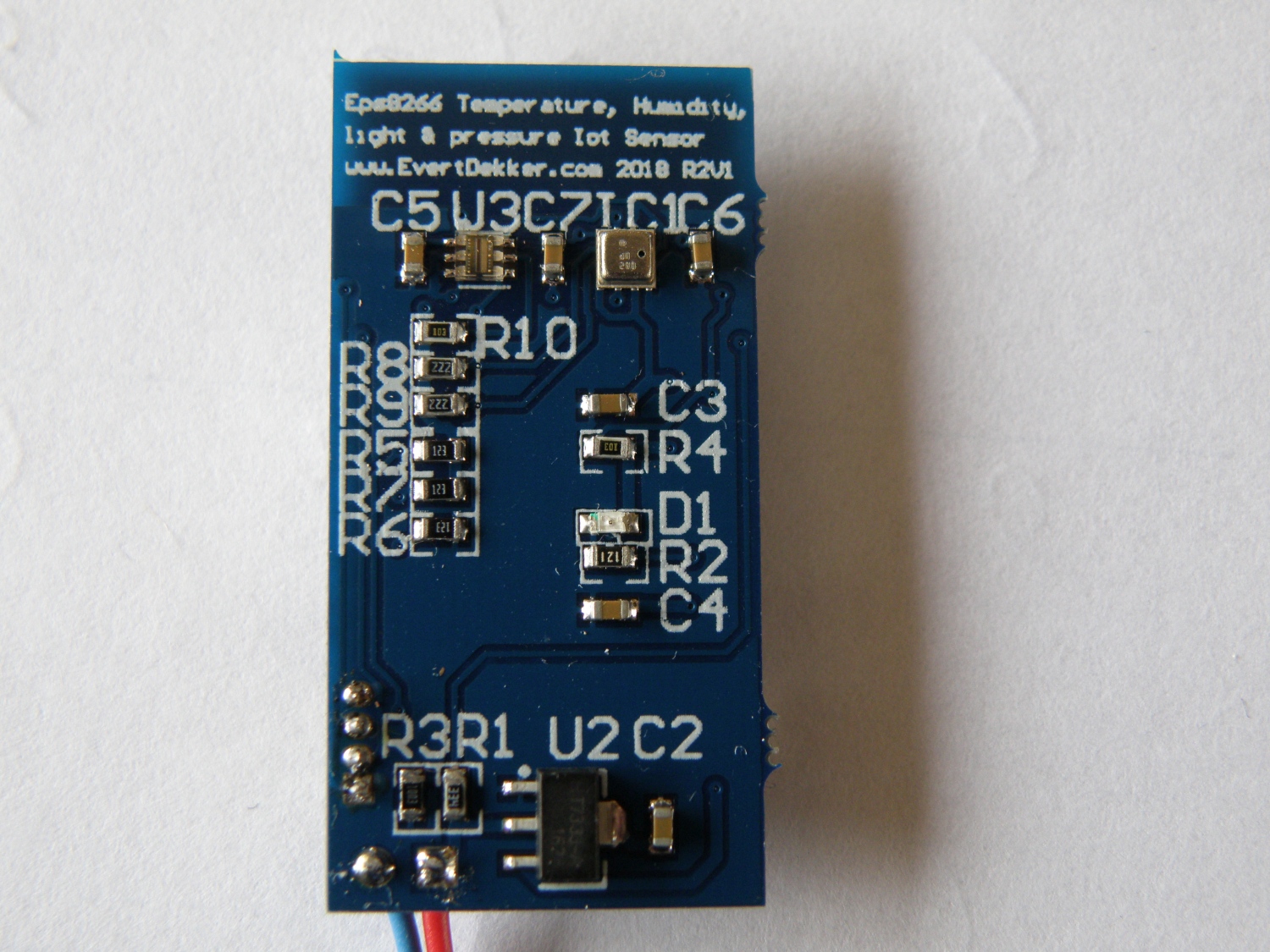
After the problems with my sensor based on the DHT22 time for a redesign, this time with the BME280 for measuring temperature, humidity and atmospheric pressure. The TSL2561 known from my light sensor node is used for measuring light level.

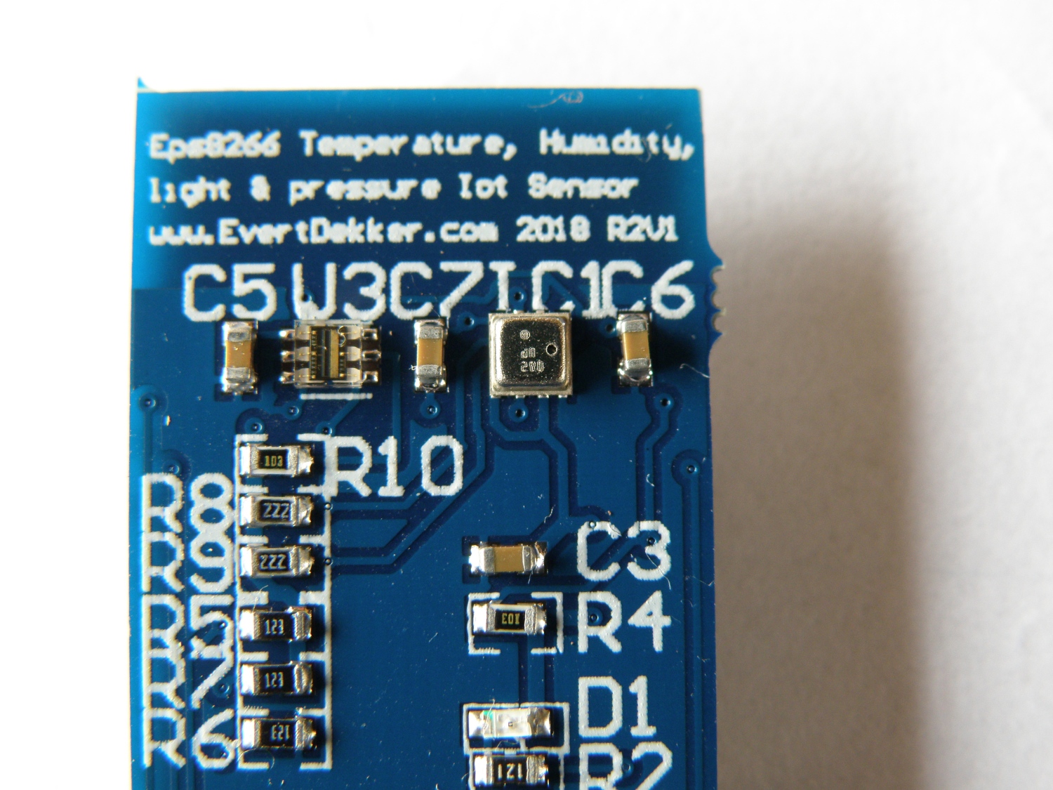
Note: it’s hard to solder the TSL2561 and it’s even harder to solder the BME280, think it over before starting on it if you want to make your own copy.
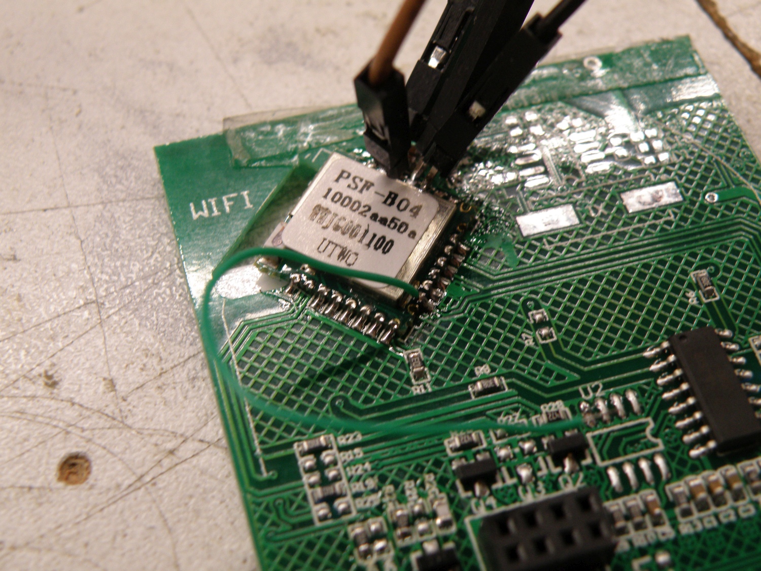
My first 4 attempts soldering the BME280 failed. With a chip this small and the small pads that are needed for it, it’s important that to all the pads there’s an equal amount of solder paste applied. If that’s not the case the whole chip rest on the pads with the most solder and will not make contact with the other pads, extra handicap is in this case that the BME280 has a metal case an will make very easy a short circuit if you use to much solder.
I have ordered now a stencil to apply the solder paste even on the pcb. To be continued….

Update 02 April 2018
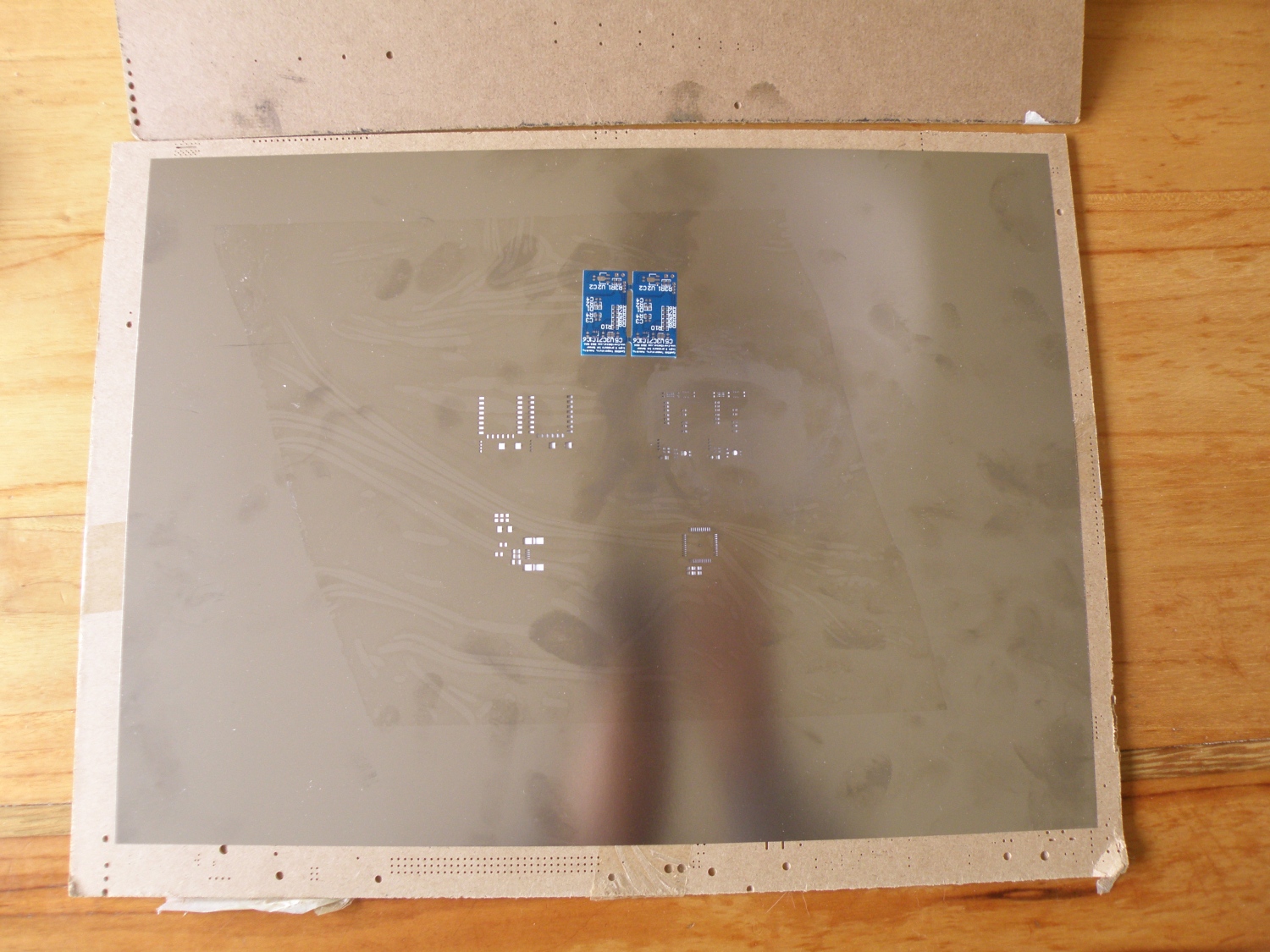
Stencil is finally in. Due the Chinese new year it took some time before they produced and shipped it. I have ordered it from Jlcpcb and it costs only $9 including shipping, unbelievable cheap.
That’s a huge stencil for such a small pcb, it didn’t even fit in the mailbox and had to collect it from the post office.
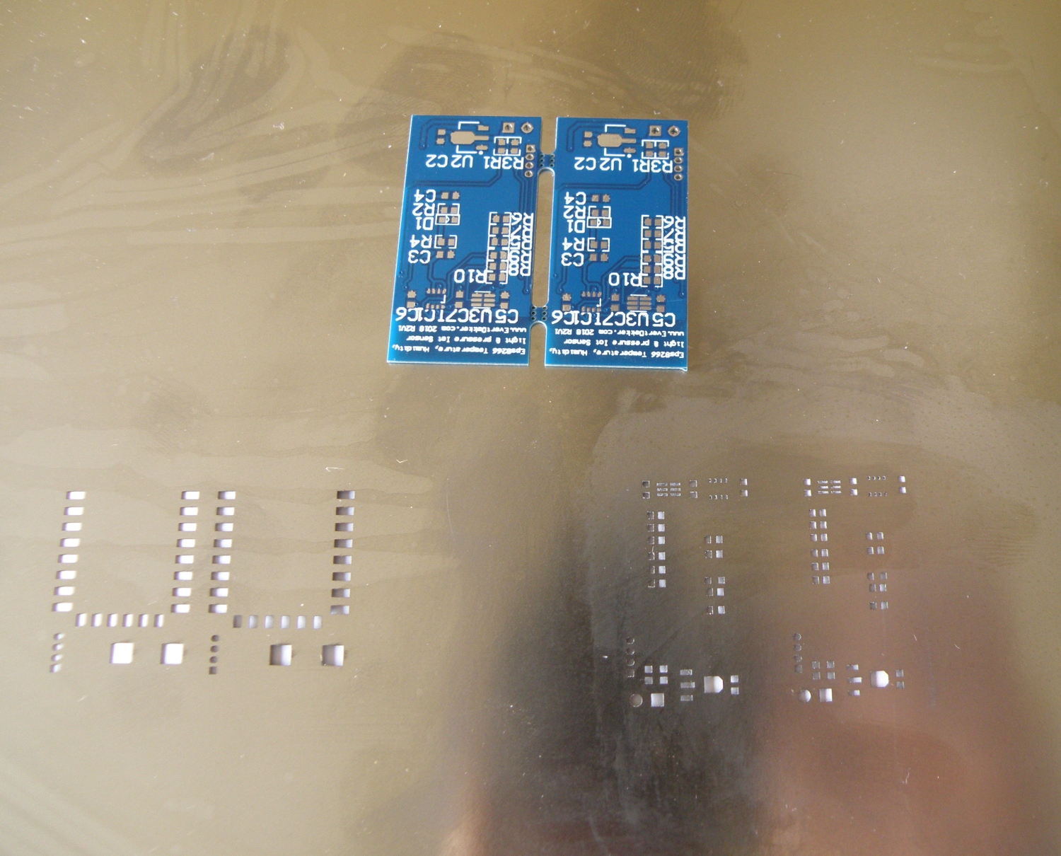
Stencil is for 2 different project’s, the upper 2 are for this project. The stencil I ordered was 100µm thick, not a standard thickness they sell, but ask for it and you will get it. Components with that small pads as the BM280 requires not to much paste, that’s why I prefer 100µm for those kind of components.
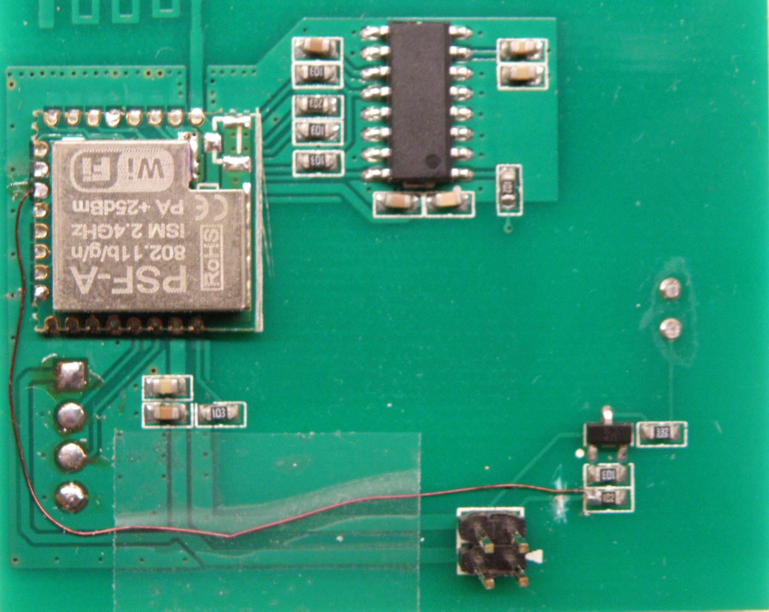
With the stencil is was easy to apply the solder paste and with the heat gun is was all soldered with ease.
Have a look at my making of the Colinkex jtag to get an idea how to apply the paste simple with not to much effort at home.

After testing every works very well. Temperature, humidity, atmospheric pressure and lux are send with the help of MQTT to the SQlite database and Node-red ones in the 2 minutes.
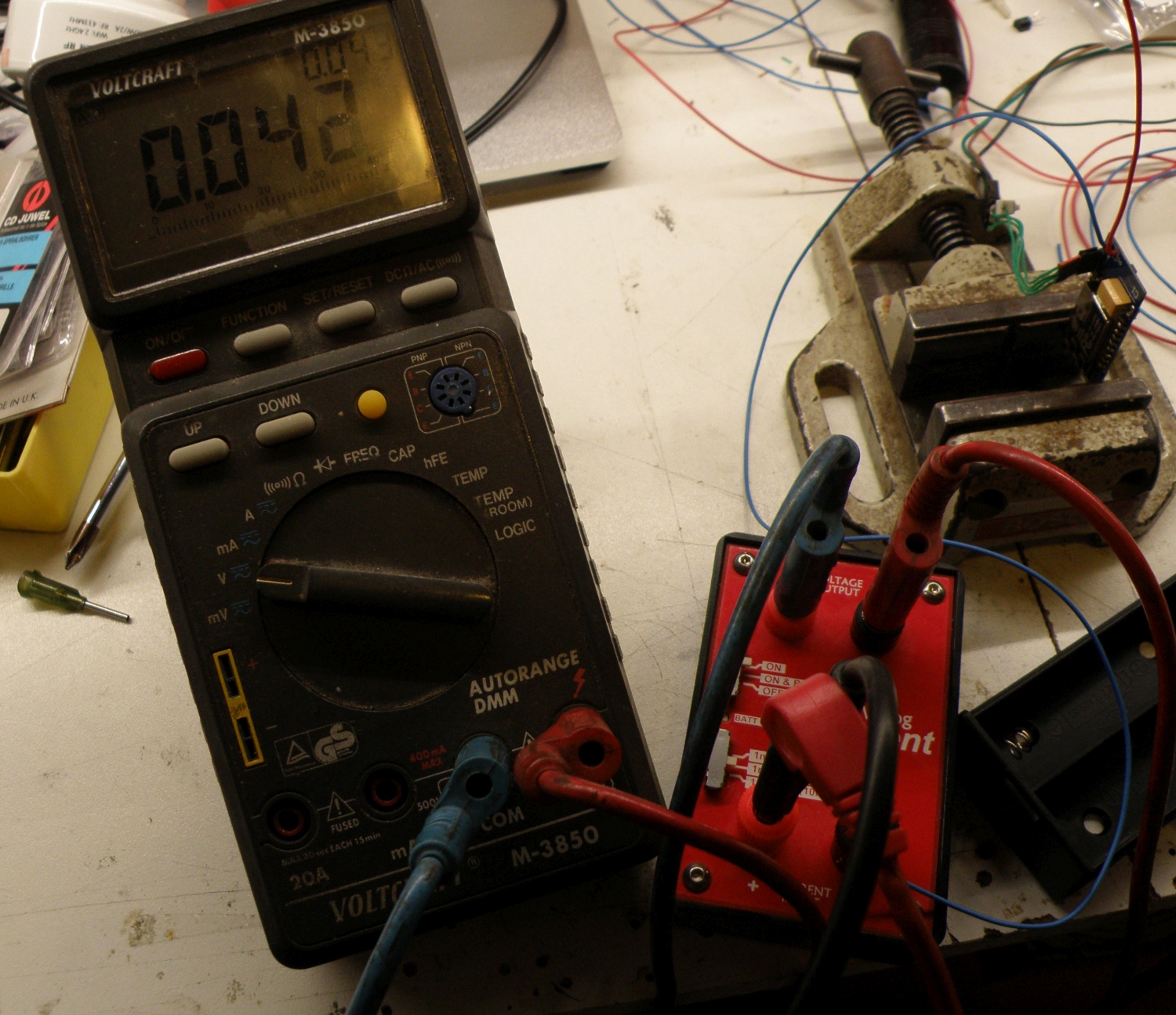
Some fine tuning in the with Arduino created software to disable the BME280 and TSL2561 just before the ESP8266 goes in deep sleep to reduce the standby power. Standby current is now 42µA, more then the sensor with the DHT22 (27µA) but good enough.
Btw, to measure the standby current that precise I used the µcurrent designed by Dave Jones from EEVblog.

Pcb Front Pcb Front
Pcb Back Pcb Back
Stencil Stencil
Stencil close up Stencil close up

Finished pcb front Finished pcb front
Finished pcb back Finished pcb back
Closeup sensors Closeup sensors
Sleep current Sleep current


You want to make your own, download the Altium Designer 16 files.

Download Now!
790 Downloads


 Comment 
  • Page 4 of 30
  • « First
  • «
  • 2
  • 3
  • 4
  • 5
  • 6
  • »
  • Last »

©2007-2020 Evert Dekker 2015 | Powered by WordPress with Easel | Subscribe: RSS | Back to Top ↑

We use cookies to ensure that we give you the best experience on our website. If you continue to use this site we will assume that you are happy with it.OkPrivacy policy